I finally have the first version built, tested, and working beautifully. There are a few changes and upgrades to be made, I should add a snubber, and move a few things slightly for easier assembly.
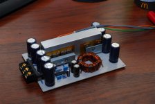
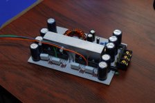
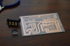
The board is single sided, single layer with NO JUMPERS. It was milled/drilled on a cnc router. The smps is based on the SG3525 to make a very simple power supply. The transformer was hand wound on an F140-77 core and operates at around 52khz. There are 4 LM3886's in a parallel setup (2 pairs) to form a 2 channel amplifier that puts out either 60x2 @ 4 ohms and 120x2 @ 2 ohms, with 28v rails or 100x2 @ 4 ohms (not 2 ohm stable) using 35v rails. A small preamp board is also in the works to allow bridging and gain adjustment. There is a solid 4.1" x 0.75" x 1.5" aluminum block in the center used as a heatsink, which also attaches to the enclosure to create a large enough heatsink, a fan might also be required because of the very small size.
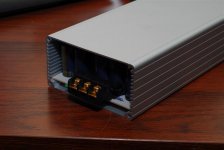
It is designed to fit inside the common hammond 1455 enclosure (don't have the exact number handy).
I'd like to release the g-code and artwork for others to make this simple amp at home once everything is perfect. It could be easily etched/milled at home and used to create small good sounding car audio amplifiers. I may even make boards available including some of the harder to find parts, like the toroid, power terminals, magnet wire etc.
Any tips or questions are welcome")
The board is single sided, single layer with NO JUMPERS. It was milled/drilled on a cnc router. The smps is based on the SG3525 to make a very simple power supply. The transformer was hand wound on an F140-77 core and operates at around 52khz. There are 4 LM3886's in a parallel setup (2 pairs) to form a 2 channel amplifier that puts out either 60x2 @ 4 ohms and 120x2 @ 2 ohms, with 28v rails or 100x2 @ 4 ohms (not 2 ohm stable) using 35v rails. A small preamp board is also in the works to allow bridging and gain adjustment. There is a solid 4.1" x 0.75" x 1.5" aluminum block in the center used as a heatsink, which also attaches to the enclosure to create a large enough heatsink, a fan might also be required because of the very small size.
It is designed to fit inside the common hammond 1455 enclosure (don't have the exact number handy).
I'd like to release the g-code and artwork for others to make this simple amp at home once everything is perfect. It could be easily etched/milled at home and used to create small good sounding car audio amplifiers. I may even make boards available including some of the harder to find parts, like the toroid, power terminals, magnet wire etc.
Any tips or questions are welcome
Attachments
nice PCB, nicely packaged arrangement.rwaudio said:There is a solid 4.1" x 0.75" x 1.5" aluminum block in the center used as a heatsink, which also attaches to the enclosure to create a large enough heatsink, a fan might also be required because of the very small size.
Fan to cool might not be enough. This is going to run very hot in the open and in a car will probably cut out on temperature protection.
AndrewT
Yes it runs a bit warm on the bench, not too hot to touch, but hotter than any other chipamp I've built, there will be a 3"x8"x0.125" aluminum spacer between the block and the enclosure, they will all be screwed together and I'll use heatsink compound so here's hoping I can't fry eggs on it. I had originally designed it to use a copper block in the center and copper spacer, but I had these on hand. And copper is getting expensive these days.
ashok
I'm using the SG3525 unregulated at 52khz running 2 IRF540's per phase (I had these on hand, but will probably switch to something with a lower rds on later) rectifiers are MUR1620CT and MUR1620CTR
I'll be happy to post the schematics and artwork for the board as soon as I know things are perfect, I don't want anyone to build the amp if there are any issues, I'm also finishing up the preamp stage with differential input etc.
After some bench testing using a 1.5" square fan and the amp hooked up to a 2.66ohm bridged load (below rated load) the amp in enclosure but without thermal grease, ranged from barely warm to warm (not hot) to the touch between idle and 1/3 power. I'll have to do some torture testing to see how hot it gets at full power, into rated load or lower. And how much ambient temperature changes affect it's cooling. I just need a higher current power supply for that testing. But sofar at room temp of about 25 deg C it actually runs much cooler than both the alpine cd player and power supply I was using for testing.
After some bench testing using a 1.5" square fan and the amp hooked up to a 2.66ohm bridged load (below rated load) the amp in enclosure but without thermal grease, ranged from barely warm to warm (not hot) to the touch between idle and 1/3 power. I'll have to do some torture testing to see how hot it gets at full power, into rated load or lower. And how much ambient temperature changes affect it's cooling. I just need a higher current power supply for that testing. But sofar at room temp of about 25 deg C it actually runs much cooler than both the alpine cd player and power supply I was using for testing.
I've been checking the enclosure AND main aluminum block, there is thermal paste between the chips and the main aluminum block, however there is no paste yet between that block, the spacer and the enclosure. With no fan the enclosure warms up very quickly and to a similar temp to the main block. There is a "good" thermal connection between all of these parts, but should get better when there is a proper layer of thermal paste between them. So at these power levels heat is not an issue, however I have not been able to run the amp higher than about 80-100watts of rms output because of the bench supply I'm using.
Stream said:Very nteresting! Waiting for the continue
Please write a little more about PS...
j.wright said:I would love some information on this project also...
J
yup..agreed!!..how is the PSU things going rwaudio? I'm just finishing my daughter's LM3886..(its just sounds awesome..) and have this urge to make one or two for my car..(no power amp, just 4x50W head unit..) love to hear some updates..thanks alot
TPS_nuB
The power supply is probably one of the simplest parts of the amp. It's based on http://sound.westhost.com/project89.htm (use the bottom schematic) which is actually a very simple to build unregulated SMPS I changed a few things to fit my application but the theory and basics can be learned there. Just make sure your traces are large enough for the current and the layout is simple with short traces or there can be instability, I actually tried to breadboard the circuit last night for another smaller project and nothing at all worked. I had to switch to a dc/dc converter for my +/- 20v so that being said the circuit CAN be picky and may not work with poor layout. The transformer I wound myself using the F-140-77 core from CWS Bytemark http://www.cwsbytemark.com/index.php?main_page=index&cPath=221
I simply used 4+4 turns on the primary made up of multiple twisted strands of fairly fine magnet wire (much easier to work with than 1 or 2 strands of heavier wire) The secondary is made of 9+9 turns using a few less strands then the primary due to the lower current. It operates at 52kHz and runs cool and noise/vibration free. The only thing I would do different next time is take better care in stripping the varnish off the leads, as I had a few strands that didn't want to solder very well at first making it a big pain to strip later. Once I get everything together I can post my version of the schematic, but it is very similar to the one linked above.
I've built 3 versions of that smps sofar, the first two being point to point wired on prototyping board, using leftover caps/transformers/connectors from dead car amps. All worked very well, the version on the breadboard was the first time this design hasn't worked perfectly for me the first try.
I can give limited help to anyone trying to build their own smps, but since it's not my design I can't garantee yours will work too.
j.wright you've got mail.
for reference here is a table giving a rough idea of the power output you can expect from a given core at a given freqency.
http://users.catchnet.com.au/~rjandusimports/tut_7a.html
for reference here is a table giving a rough idea of the power output you can expect from a given core at a given freqency.
http://users.catchnet.com.au/~rjandusimports/tut_7a.html
- Status
- This old topic is closed. If you want to reopen this topic, contact a moderator using the "Report Post" button.
- Home
- Amplifiers
- Chip Amps
- Car audio LM3886 + SMPS on single sided board