hi all, thanks for the update rwaudio, checked the link..well how can I missed that one?..I'm a regular visitor of ESP..not an EE though-have major difficulties understanding things  , but really loves DIY & audio. I'll try to have 4x50w LM3886-car for a start..wish me luck
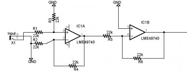
, but really loves DIY & audio. I'll try to have 4x50w LM3886-car for a start..wish me luckAndrewT or anyone who's implimented a differential input could you give me a little help with my differential input? Basically I only get good operation when I connect the rca shield directly to signal ground. Using a cap/resistor (tried many values of each) gave increased noise, though slightly better than nothing connected.
As you can tell I'm new to using a differential input, attached is a simple version of what I have on the breadboard right now. Power supply is taken from the output of the amps smps and regulated to +/- 15v.
It's pretty good at rejecting noise from a very crappy bench power supply (completely unusable using normal input buffer, and very listenable with slight noise using the differential input) and it's pretty much silent using my regulated bench supply, however I'm assuming that some cars "could" be more like the noisy bench supply.
I'm also not sure how to impliment a dc blocking cap on the input, if it's as simple as putting a large enough film cap on the signal line before the 22k resistor.
Attachments
Is it not a differential input if the rca shield to ground connection is removed? That's where I need help since that schematic is the only way I could get silent operation using a noisy supply.
The source at the moment is a typical car cd player (alpine cda-9813) so it's expecting a "normal" input.
The source at the moment is a typical car cd player (alpine cda-9813) so it's expecting a "normal" input.
Thanks AndrewT, is there a good fairly noise free topology to use for amplifier input? I'll probably be making a few of these for friends etc, and most of them don't have the best quality stereo's. I'd like these to work well and engine noise free, atleast the best I can create.
Hello everyone, I haven't cleaned up the schematic yet so I can't post that. But I do have a 99% complete BOM (this does NOT include parts for the preamp board, this is amp/power supply only) The idea of having the preamp board seperate from the main board is for almost unlimited configurability. If you want crossovers, or balanced input or whatever you can imagine, it can be added to the amp. I will be designing a couple versions, simple input, and probably highpass or lowpass crossovers.
Please note, that this version is intended for a subwoofer amplication, as many people have found the large rail capacitors I chose may not provide the best possible sound quality in a mid/hi freqency application, some trial and error may be required.
Please note, that this version is intended for a subwoofer amplication, as many people have found the large rail capacitors I chose may not provide the best possible sound quality in a mid/hi freqency application, some trial and error may be required.
Attachments
ide2003 try and make sure the ferrite toroid is suitable for a transformer. Yes I'm using the SG3525, it is simple to use and setup and works fairly well.
Almost all parts listed on the BOM are what I actually used to build the first version (other than the C12, C13 which I had many 1000uf caps on hand and the fuse holder which wasn't part of the pcb when I milled the first one since I used external fusing for testing)
Do you have a method of etching/milling your own pcb? it almost defeats the purpose to have these made at a board house because it was designed as single layer for diy use.
rwaudio said:ide2003 try and make sure the ferrite toroid is suitable for a transformer. Yes I'm using the SG3525, it is simple to use and setup and works fairly well.
Almost all parts listed on the BOM are what I actually used to build the first version (other than the C12, C13 which I had many 1000uf caps on hand and the fuse holder which wasn't part of the pcb when I milled the first one since I used external fusing for testing)
Do you have a method of etching/milling your own pcb? it almost defeats the purpose to have these made at a board house because it was designed as single layer for diy use.
thanks for your tips rwaudio, I haven't checked the toroid yet but the size is about correct, my friend have used them for radar baloon? (don't quite understand this)..as for the pcb should be no problem, I have built a mini cnc for small parts..back in 2005, still working well

TeguhPS
ide2003 are you using mach3 on your mini cnc?
if so I can send you the g-code directly when it's finished since that's what I use on my cnc machine.
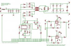
Attached is the first version of the schematic, I haven't double checked everything yet so please use it for reference or learning. Please don't build from that schematic yet until I am able to confirm it. Also snubbers will probably be added to both the power supply and amplifier outputs.
if so I can send you the g-code directly when it's finished since that's what I use on my cnc machine.
Attached is the first version of the schematic, I haven't double checked everything yet so please use it for reference or learning. Please don't build from that schematic yet until I am able to confirm it. Also snubbers will probably be added to both the power supply and amplifier outputs.
Attachments
rwaudio said:ide2003 are you using mach3 on your mini cnc?
if so I can send you the g-code directly when it's finished since that's what I use on my cnc machine.
Attached is the first version of the schematic, I haven't double checked everything yet so please use it for reference or learning. Please don't build from that schematic yet until I am able to confirm it. Also snubbers will probably be added to both the power supply and amplifier outputs.
Thanks for the schematic rwaudio-really appreciated it-I know, I have to study a lot before building your PSU
I have also checked many threads in power supply here-it's not easy-needs a lot of good help, from you here and my EE friend.
I'm still using the turbocnc 4.2, my dynabook is too slow for mach3, but gcode is very welcome
TPS
Hello. Can You help me with selecting right ferrite core. I did not found the same core as you used...
The list of availible cores is here:
http://www.promelec.ru/catalog_info/54/132/523/292/
Here are dimensions : OD*Id*H
And here is parametres of cores:
http://www.promelec.ru/catalog_info/54/132/522/290/
Thanks.
The list of availible cores is here:
http://www.promelec.ru/catalog_info/54/132/523/292/
Here are dimensions : OD*Id*H
And here is parametres of cores:
http://www.promelec.ru/catalog_info/54/132/522/290/
Thanks.
Hello Stream,
I had a look at both of those pages, but I'm not a ferrite expert. I don't know if those cores are close enough to the type 77 that most people recommend. Here is a page that lists a little more info on the core I chose I hope that helps.
http://www.bytemark.com/products/fermat77.htm
I'm using the F140-77
You might try contacting the company from the links you listed and ask them for a core suitable for SMPS or reference the type 77 core and ask if they have something comparable.
- Status
- This old topic is closed. If you want to reopen this topic, contact a moderator using the "Report Post" button.
- Home
- Amplifiers
- Chip Amps
- Car audio LM3886 + SMPS on single sided board