Hi, the first thing I should say is I am new to the world of DIY audio, so goes easy on me.
I have been doing a lot of reading up and started to build a LM1875 amp. I have already got two mono LM1875 kits (and soldered them), a very nice Modu enclosure, and all the back panel connectors.
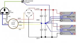
I am now moving on to building the power supply. After reading many articals in these forums and a few guides this is the circuit I have come up with:
As you can see I have opted for a 160VA, single 230V primary, dual 18V secondary toroid transformer. Along with two bridge rectifiers and 4,700uF capacitors for smoothing.
So basically, do I have the wiring all correct? Specifically do I have the grounding of the signal and mains correct?
I have been doing a lot of reading up and started to build a LM1875 amp. I have already got two mono LM1875 kits (and soldered them), a very nice Modu enclosure, and all the back panel connectors.
I am now moving on to building the power supply. After reading many articals in these forums and a few guides this is the circuit I have come up with:
An externally hosted image should be here but it was not working when we last tested it.
As you can see I have opted for a 160VA, single 230V primary, dual 18V secondary toroid transformer. Along with two bridge rectifiers and 4,700uF capacitors for smoothing.
So basically, do I have the wiring all correct? Specifically do I have the grounding of the signal and mains correct?
Looks good to me! The only thing you may want to experiment with (and there are a LOT of opinions on this) is the amount of capacitance you use. Also, you may or may not want to try a snubber power supply, which adds a series resistor and capacitor in parallel with the main capacitor.
2channels fed from +-4700uF is getting close to Peter Daniel's implementation.
Except he uses 96dB speakers and locates the smoothing (1500 to 2200uF) on each amp PCB.
Either go PD's route or go Carlos FM's version. Completely different ways to approach the PSU.
Only power up your project through a mains light bulb tester, until you KNOW it is wired correctly.
Use the light bulb tester each time you add on the next stage or modify any stage.
I suggest you power up the mains transformer alone, then add the rectifiers and check again. Then add the smoothing and check again, etc.
Thanks for the quick reply. I was thinking of perhaps having four 2,200uF caps instead of two 4,700uF as some people on the forums said it gave them better results.
My next question is, do i "need" the connection from the ground coming out of the power suppy to the mains earth screwed to the enclosure?
My next question is, do i "need" the connection from the ground coming out of the power suppy to the mains earth screwed to the enclosure?
if you decide to go this route then read Peter Daniel's construction guide and his advice on building your chipamp.simonlarusso said:I was thinking of perhaps having four 2,200uF caps instead of two 4,700uF as some people on the forums said it gave them better results.
You need to connect the earth to anything conductive that can be touched without the need of any tool. That is the enclosure, can be the heatsinks, if they are mounted outside of the enclosure and so on.simonlarusso said:My next question is, do i "need" the connection from the ground coming out of the power suppy to the mains earth screwed to the enclosure?
The connection from earth to the internal ground should be made, if no other component in your audio chain has one. It serves to improve ground stability and noise immunity. It can be omitted, if another component in your chain already has such a connection, because then you may get ground loops that lead to hum.
Professional equipment often comes with a ground lift switch that leaves a choice for both cases.
The important point is that the earth connection to the exposed parts must never be interrupted as long as the amplifier is plugged into mains.
AndrewT said:Only power up your project through a mains light bulb tester, until you KNOW it is wired correctly.
Use the light bulb tester each time you add on the next stage or modify any stage.
I suggest you power up the mains transformer alone, then add the rectifiers and check again. Then add the smoothing and check again, etc.
Yes I am going to make a bulb tester, this is simply a 100W bulb added to the "Live" wire of the power cable and all in an insulated box of course?
pacificblue said:Your schematic looks correct. How about using fuses also on the secondary side?
The kits I bought have a fuse on both the +25V and -25V as part of the PCB design.
AndrewT said:if you decide to go this route then read Peter Daniel's construction guide and his advice on building your chipamp.
Ok thanks, I will do a bit more research and decide on what values I will use for smoothing caps.
pacificblue said:
You need to connect the earth to anything conductive that can be touched without the need of any tool. That is the enclosure, can be the heatsinks, if they are mounted outside of the enclosure and so on.
The connection from earth to the internal ground should be made, if no other component in your audio chain has one. It serves to improve ground stability and noise immunity. It can be omitted, if another component in your chain already has such a connection, because then you may get ground loops that lead to hum.
Professional equipment often comes with a ground lift switch that leaves a choice for both cases.
The important point is that the earth connection to the exposed parts must never be interrupted as long as the amplifier is plugged into mains.
Perfect, thanks for the explaination. Being new to this I have a lot of silly answers that keep popping up.
Ok, thanks for all your replies. I have slighty modified the circuit and think I might just use one bridge rectifier as this will be simpler to build and keep cost down. This is my new schematic:
An externally hosted image should be here but it was not working when we last tested it.
As I said above I have not commited to what cap values to use yet. So is it all correct?
Thanks in advance
post 12 shows the Audio Ground combined with the smoothing cap zero volt. DON'T.
Keep the smoothing cap charging pulses within their own (figure of 8) loop that runs from transformer to rectifier to caps and back again. Take a single short wire from zero volt to the Audio Ground.
Post 11 is wrong. A single rectifier works just as well with either a centre tapped or a dual secondary wired as a centre tapped.
The advantage of the dual rectifier on a dual secondary is the ability to keep each channel's Audio Ground separate and use a disconnecting network to connect each Audio Ground back to the Safety Earth. This option is not shown in any of your diagrams.
Start with a smaller bulb (40W) and progressively increase to what is required to stay unlit as each piece is added on. Starting with the big wattage could damage something if the wiring or semiconductors are wrong.
pacificblue said:Use a single bridge rectifier with a center-tapped transformer. A dual secondary transformer (as drawn) is better combined with one rectifier per winding.
Oh ok, but does a dual secondary type still work with one brdge rectifier?
Also can you get centre tapped toroidal type transformers as I can't seem to find one on the website I will be ordering from?
Thanks for all the information so far guys. I have been reading Peter Daniel's tutorial/thread and think I am going to use two bridge recifiers. I have changed my schematic to use a star grounding:
Is this one ok and where would I put the smoothing capacitors in this configuration? In fact do I need smoothing caps or are they recommended?
An externally hosted image should be here but it was not working when we last tested it.
Is this one ok and where would I put the smoothing capacitors in this configuration? In fact do I need smoothing caps or are they recommended?
Post #11 is correct. It recommends the two out of four possible choices that make most sense.
You need smoothing capacitors. Their placement is as recommended in post #3.
Your choices are
You need smoothing capacitors. Their placement is as recommended in post #3.
Your choices are
- - gainclone style with only one 1000 µF smoothing capacitor per rail (can vary from 220 to 2200 µF according to taste) as near to the LM3886 as possible.
- datasheet style with 0,1 µF directly at the LM3886's power supply pins, 10 µF as near to them as possible on the PCB, 1000 µF not too far away also on the PCB, and greater than or equal to 10.000 µF off the PCB in your PSU.
- high-end style with lots of capacitors in all shapes and sizes, lovingly placed along a complex pattern, supported by bleeder resistors and snubber networks, all components chosen after careful listening tests, yet everybody uses different ones according to personal taste. For an example search for CarlosFM snubberized power supply.
justify this statement.pacificblue said:A dual secondary transformer (as drawn) is better combined with one rectifier per winding.
The use of a single bridge rectifier for both windings makes it a full-wave-rectifier for each rail. In German that is called "two-way-rectifier", which makes its working principle clearer. The other application is a bridge rectifier for each rail.
With bridge rectifiers the effective load the secondaries pose for the primaries is 1,41 times smaller than with full-wave-rectification. The reason is that in the full-wave-circuit current is only flowing through each winding during one half-cycle, while with bridge rectification current flows during both half-cycles. The resulting lower load for the primaries is good for the transformer's regulation. It leaves more headroom until saturation. And it compensates for the efficiency loss that double as many diodes in the current path produce through their forward voltage drop.
Another advantage was explained by Mr. Nelson Pass.
A possible third advantage was described by yourself in post #13.
Regards
David
With bridge rectifiers the effective load the secondaries pose for the primaries is 1,41 times smaller than with full-wave-rectification. The reason is that in the full-wave-circuit current is only flowing through each winding during one half-cycle, while with bridge rectification current flows during both half-cycles. The resulting lower load for the primaries is good for the transformer's regulation. It leaves more headroom until saturation. And it compensates for the efficiency loss that double as many diodes in the current path produce through their forward voltage drop.
Another advantage was explained by Mr. Nelson Pass.
Originally posted by Nelson Pass
Most customers want total silence from the amplifier, including
mechanical noise. If there is not complete matching between the
secondary coils and only 1 rectifier bridge, any net DC imbalance
between the current of the + supply and the - will tend to
saturate the core of the transformer and create noise. This is
seen for quite low current differences and can also show up with
low frequency output. Using two bridges eliminates the problem.
A possible third advantage was described by yourself in post #13.
Regards
David
Explain why? It is the checked up scheme. I have made many amplifiers on LM under this scheme, they work wery well and sound is good.AndrewT said:post 12 shows the Audio Ground combined with the smoothing cap zero volt. DON'T.
- Status
- This old topic is closed. If you want to reopen this topic, contact a moderator using the "Report Post" button.
- Home
- Amplifiers
- Chip Amps
- Help with first Power Supply for LM1875