In a centre-tapped transformer current will only flow in one half of the winding during one half-cycle. If you use a dual secondary tranformer with full-wave rectification, i. e. one rectifier bridge per [each] secondary, current will flow in each secondary during both half-cycles. That leads to a higher efficiency for the dual secondary version.
And lower voltage. With dual secondaries you can decrease the transformer amperage rating by the same proportion of the voltage drop. That's not relevant to efficiency on an amplifier of this scale.
Steady tone figures are either irrelevant or the steady tone is an accident, in which case the device is morbidly inefficient.
That doesn't relate to a design goal.
LM1875's have a too-small tolerance for current, thus limiting the importance of current by that amount. With its a too-small resource and too-large job, it must get by on charge. So, what is the most efficient power supply for charge?
Consider the amperage limit. Consider the voltage limit of 26.5+26.5vdc (long term testing cannot pass this figure). Consider that the LM1875 can vary between 28 watts and 89 watts reliant on charge, you could say that the charge is more important the the current by that extent. Perhaps it could perform better with a relevant power supply?
. . .
Midpoint connection: Pt / Pdc = 1,5
Bridge rectification: Pt / Pdc = 1,23
. . .
After rectifier, these figures are in proportion to the voltage output (albeit slightly above average diodes they would be).
The smaller amperage dual secondaries making less voltage or the larger amperage center tap making more voltage. . .
I can't identify a description of efficiency with that.
Hey, long time no see.
Right. The current decrease that corresponds to the additional ~1 V voltage drop is pretty negligible.
Did you ever hear the piece 'Thus spoke Zarathustra' by Richard Strauss live? It starts with a 20 s long continuous sub-contra C from an organ. You have to hear it live, because most speakers will not reveal that tone at all. It has a frequency of 16,35 Hz and even 12" speakers have a hard time to replace enough air to make it as much as audible, even less reproduce it at realistic levels. Not an accident at all, but the composer's choice to represent nature in musical form.
I don't understand the meaning of this. You have to put in more, than what you want to come out. The transformer must supply more power than the amplifier consumes as an average. Even big capacitors can only buffer signals that are above the transformers power rating only for a very short time.
Power supply efficiency does not depend on what it supplies power to. For each application you need to find the right compromise. A power supply that supplies exactly the necessary amount of power is efficient in that every machine has its highest efficiency at its nominal power. E. g. a transformer may have 70 % efficiency at its nominal power, but only 50 % efficiency at 70 % of its power. Don't nail me on those numbers, they are only there to explain the principle. A big power supply is efficient in that bigger transformers generally have a higher efficiency than smaller ones. E. g. a small transformer may have 70 % efficiency at nominal power, while a bigger transformer may be 80 % efficient. If you want to improve the efficiency, you will not get around calculating, whether a specific application is better off with a fit-to-size transformer or an oversized one.
Power supplies do not have a sweet spot in the sense that too much is bad for the sonic performance. If you want a certain amount of output power, there is a minimum size of power supply you need. Let me put it in an exaggerated way and ignoring other aspects that also determine transformer and capacitor sizes. If you listen to music with little dynamics, use a big transformer and small capacitors. If you listen to very dynamic music, choose a small transformer and big capacitors. For an amplifier that works well with any type of music, use a big transformer and big capacitors.
Efficiency is the relation of power input to power output. If you need to draw 150 W from the grid to get 60 W from the amplifier that is less efficient (eta = 0,4 or 40 %) than if you only draw 123 W from the grid and also get 60 W from the amplifier (eta = 0,49 or 49 %).
And lower voltage. With dual secondaries you can decrease the transformer amperage rating by the same proportion of the voltage drop. That's not relevant to efficiency on an amplifier of this scale.
Right. The current decrease that corresponds to the additional ~1 V voltage drop is pretty negligible.
Steady tone figures are either irrelevant or the steady tone is an accident, in which case the device is morbidly inefficient.
Did you ever hear the piece 'Thus spoke Zarathustra' by Richard Strauss live? It starts with a 20 s long continuous sub-contra C from an organ. You have to hear it live, because most speakers will not reveal that tone at all. It has a frequency of 16,35 Hz and even 12" speakers have a hard time to replace enough air to make it as much as audible, even less reproduce it at realistic levels. Not an accident at all, but the composer's choice to represent nature in musical form.
With its a too-small resource and too-large job, it must get by on charge.
I don't understand the meaning of this. You have to put in more, than what you want to come out. The transformer must supply more power than the amplifier consumes as an average. Even big capacitors can only buffer signals that are above the transformers power rating only for a very short time.
So, what is the most efficient power supply for charge?
Power supply efficiency does not depend on what it supplies power to. For each application you need to find the right compromise. A power supply that supplies exactly the necessary amount of power is efficient in that every machine has its highest efficiency at its nominal power. E. g. a transformer may have 70 % efficiency at its nominal power, but only 50 % efficiency at 70 % of its power. Don't nail me on those numbers, they are only there to explain the principle. A big power supply is efficient in that bigger transformers generally have a higher efficiency than smaller ones. E. g. a small transformer may have 70 % efficiency at nominal power, while a bigger transformer may be 80 % efficient. If you want to improve the efficiency, you will not get around calculating, whether a specific application is better off with a fit-to-size transformer or an oversized one.
Consider the amperage limit. Consider the voltage limit of 26.5+26.5vdc (long term testing cannot pass this figure). Consider that the LM1875 can vary between 28 watts and 89 watts reliant on charge, you could say that the charge is more important the the current by that extent. Perhaps it could perform better with a relevant power supply?
Power supplies do not have a sweet spot in the sense that too much is bad for the sonic performance. If you want a certain amount of output power, there is a minimum size of power supply you need. Let me put it in an exaggerated way and ignoring other aspects that also determine transformer and capacitor sizes. If you listen to music with little dynamics, use a big transformer and small capacitors. If you listen to very dynamic music, choose a small transformer and big capacitors. For an amplifier that works well with any type of music, use a big transformer and big capacitors.
I can't identify a description of efficiency with that.
Efficiency is the relation of power input to power output. If you need to draw 150 W from the grid to get 60 W from the amplifier that is less efficient (eta = 0,4 or 40 %) than if you only draw 123 W from the grid and also get 60 W from the amplifier (eta = 0,49 or 49 %).
Hi man! Thanks for the reply!Hey, long time no see.
Yes, that does take current. Charge would run out during organ bass. There's almost no way to cheat when the bass notes are so big and so long.. . .
Did you ever hear the piece 'Thus spoke Zarathustra' by Richard Strauss live? It starts with a 20 s long continuous sub-contra C from an organ. You have to hear it live, because most speakers will not reveal that tone at all. It has a frequency of 16,35 Hz and even 12" speakers have a hard time to replace enough air to make it as much as audible, even less reproduce it at realistic levels. Not an accident at all, but the composer's choice to represent nature in musical form.
")
. . . You have to put in more, than what you want to come out. The transformer must supply more power than the amplifier consumes as an average. Even big capacitors can only buffer signals that are above the transformers power rating only for a very short time.
I cannot figure out how to explain without getting terribly mixed up. All that I can say is that two near identical amplifiers with the same current, same wattage rating, same power supply board, same transformer, can differ on pulse power output by about 300% because of charge and other efficiencies. I'd love to know why but I probably couldn't understand the math.
Power supply efficiency does not depend on what it supplies power to. For each application you need to find the right compromise. A power supply that supplies exactly the necessary amount of power is efficient in that every machine has its highest efficiency at its nominal power. E. g. a transformer may have 70 % efficiency at its nominal power, but only 50 % efficiency at 70 % of its power. Don't nail me on those numbers, they are only there to explain the principle. A big power supply is efficient in that bigger transformers generally have a higher efficiency than smaller ones.
Although most documents say that a linear power supply is only efficient at maximum. . . instead, I believe you are correct.
I think that you said its efficient up until the make/break point of additional noise.
E. g. a small transformer may have 70 % efficiency at nominal power, while a bigger transformer may be 80 % efficient. If you want to improve the efficiency, you will not get around calculating, whether a specific application is better off with a fit-to-size transformer or an oversized one.
Desired output at the speaker jack comes into play. For full linear audio amp, chances are good that the larger transformer will be more efficient at facilitating the necessary tasks.
Power supplies do not have a sweet spot in the sense that too much is bad for the sonic performance. If you want a certain amount of output power, there is a minimum size of power supply you need. Let me put it in an exaggerated way and ignoring other aspects that also determine transformer and capacitor sizes. If you listen to music with little dynamics, use a big transformer and small capacitors. If you listen to very dynamic music, choose a small transformer and big capacitors. For an amplifier that works well with any type of music, use a big transformer and big capacitors.
Hmm. There so much to this that I don't know. But, results support your statement quite well.
Um, but a Far too large transformer will need a large RC network, and that could reduce efficiency a bit.
Efficiency is the relation of power input to power output. If you need to draw 150 W from the grid to get 60 W from the amplifier that is less efficient (eta = 0,4 or 40 %) than if you only draw 123 W from the grid and also get 60 W from the amplifier (eta = 0,49 or 49 %).
We almost agree, but the scope is different. . . I think that Efficiency relates to power in at the plug spent towards desirable output at the speaker cone. And, that power really should have a purpose.
This applies nicely to this thread because chipamps are most suited to active speakers, since the chipamp design is sealed shut inside the chip, thus whatever workarounds aren't with the power circuit are with the speaker itself.
Thank you for the cohesive reply. It makes sense and some of it relates directly to my question on charge. Its the dynamics! When the transients on LM1875 can shoot up to 89 watts, that's a heck of a lot of charge. I'm not so familar with that topic, but it seems important for an amplifier with such limited resources to have every resource you can give it and also important to make the difference between an exciting "its like live" presentation versus boredom listening "to" "canned" audio of a speaker. Can you expand your comments on power supply construction and its effect on dynamics?
does this mean anything to anyone else?And lower voltage. With dual secondaries you can decrease the transformer amperage rating by the same proportion of the voltage drop. That's not relevant to efficiency on an amplifier of this scale.
Steady tone figures are either irrelevant or the steady tone is an accident, in which case the device is morbidly inefficient.
That doesn't relate to a design goal.
LM1875's have a too-small tolerance for current, thus limiting the importance of current by that amount. With its a too-small resource and too-large job, it must get by on charge. So, what is the most efficient power supply for charge?
Consider the amperage limit. Consider the voltage limit of 26.5+26.5vdc (long term testing cannot pass this figure). Consider that the LM1875 can vary between 28 watts and 89 watts reliant on charge, you could say that the charge is more important the the current by that extent. Perhaps it could perform better with a relevant power supply?
Or is this another example of Daniel's version of the physics and science behind electron flow?
Last edited:
two near identical amplifiers with the same current, same wattage rating, same power supply board, same transformer, can differ on pulse power output by about 300% because of charge and other efficiencies. I'd love to know why but I probably couldn't understand the math.
That sounds very improbable. What exactly are the differences between those amplifiers.
Try to explain, what you think 'charge' is. From a technical point of view it is the energy that is stored in the capacitors, and if you have the same power supply board and same transformer, the charge will be the same.
Although most documents say that a linear power supply is only efficient at maximum.
Not only. It is most efficient at maximum.
I think that you said its efficient up until the make/break point of additional noise.
Efficiency is not a digital concept that is either on or off, but an analog concept that is higher or lower, but rarely zero and never 100 % as far as human knowledge goes. Depending on the actually used output power there are situations, where the smaller transformer has a higher efficiency, and others, where the bigger one is more efficient. For an amplifier design you need to assess, in which situation the amplifier will mostly be used. Or you can simply assume that the differences are not big enough to worry much about. The difference in efficiency from one transformer to another is far from the gain in efficiency you can get from an SMPS. But even SMPS have their best efficiency at their nominal rating and many fall short, when you use them at very low powers, like the usual listening level of an amplifier at home.
Desired output at the speaker jack comes into play. For full linear audio amp, chances are good that the larger transformer will be more efficient at facilitating the necessary tasks.
Transformer size limits the achievable output power.
Um, but a Far too large transformer will need a large RC network, and that could reduce efficiency a bit.
Only the R part of the RC network would reduce efficiency, but transformer size and the need for an RC network are not directly related.
Can you expand your comments on power supply construction and its effect on dynamics?
Dynamics refer to the difference between the lowest and the loudest sound. The question you have to answer for yourself is, are those changes fast or slow and do they happen often or seldom in the music you listen to. When you listen to organ concerts you have very loud passages that remain loud for a long time. When you listen to a drum solo, you get lots of short peaks. To remain with my simplified comments from above, you need a big transformer and small capacitors for the organ and a small transformer with big capacitors for the drums. Use a big transformer and big capacitors, if you want to listen to either instrument every now and then.
If transformer and capacitors have a reasonable size you won't gain much by stepping them up further. Once the transformer rating is three times the amplifier output power and the capacitors are in the tens of thousands of µF range, you will in most cases have achieved what dynamics you can get out of an amplifier. It is the usual game of diminishing returns.
The LM1875 like all chipamps has a voltage rating that limits, what dynamics you can achieve and a current limiter that also restricts, how much dynamics you can achieve. If that IC cannot fulfill your expectations, you need a different amplifier with higher voltage rating and a current limiter with higher threshold or no current limiter at all. Or more efficient speakers.
I was in error--The power supply board is different in order to make factor 3x difference in dynamics between two similar amplifiers.That sounds very improbable. What exactly are the differences between those amplifiers.
I seem to have SMPS fall short in a different way.. . .But even SMPS have their best efficiency at their nominal rating and many fall short, when you use them at very low powers, like the usual listening level of an amplifier at home.
. . .The question you have to answer for yourself is, are those changes fast or slow and do they happen often or seldom in the music you listen to. When you listen to organ concerts you have very loud passages that remain loud for a long time. When you listen to a drum solo, you get lots of short peaks. To remain with my simplified comments from above, you need a big transformer and small capacitors for the organ and a small transformer with big capacitors for the drums. Use a big transformer and big capacitors, if you want to listen to either instrument every now and then.
. . .
An excellent clue! Thank you very much!!!
Perhaps: bridge rectifier > big caps > slight resistance > small caps > amp ?
The LM1875 like all chipamps has a voltage rating that limits, what dynamics you can achieve and a current limiter that also restricts, how much dynamics you can achieve. If that IC cannot fulfill your expectations, you need a different amplifier with higher voltage rating and a current limiter with higher threshold or no current limiter at all. Or more efficient speakers.
Or a fet?
It's just "Daniel's World" engineering.
My hope is that its not boring.
Perhaps: bridge rectifier > big caps > slight resistance > small caps > amp ?
That reduces ripple and rail voltage. You will have slightly less dynamics, but may still get better sound thanks to reduced power supply noise.
Or a fet?[/QUOTE]
Which makes it a different amplifier.
Question: Since Lm1875 is an opamp, can it be used in a circuit like this, but yet scaled up to drive a speaker?: HDOA - High Dynamics Op AmpWhich makes it a different amplifier.
That reduces ripple and rail voltage. You will have slightly less dynamics, but may still get better sound thanks to reduced power supply noise.
So, this example does simply more powerful audio via avoiding amplification of power supply noise (its finite resources doing more audio, less noise). Its a basic increase of efficiency?
Okay, so how do we do both "slightly more dynamics" and also less noise at the same time?
yes, of course. It's a standard circuit you find in textbooks. Mostly done as power amp with TDA2030 which is almost equal to the LM1875.
Just an OT question Daniel, you are writing or have written your bac paper/thesis? What's your discipline?
Regards
Many papers written in my youth, when I was in college, and absolutely none of them were of any personal interest.
Discipline is computer network engineer. As a theme, I'll either push a problem until it breaks or is repaired and either way gets repaired--half measures grieve me greatly.
The reason that I would obsess over LM1875 is because it doesn't fall short on anything except for output power. And, except for output power, its the chipamp that doesn't compromise fidelity. Usually, the harmonic output of LM1875 amplifiers is just the sort that you'd like to increase by bridging, but the current rating is too little unless you have 16 ohm speakers.
Okay, so how do we do both "slightly more dynamics" and also less noise at the same time?
More dynamics
-> higher rail voltage in all load situations = big transformer and big low ESR capacitors.
-> efficient speakers.
Less noise
-> big capacitors or
-> cascaded RC circuits as per your post #88 or
-> LC circuits as recommended by Nelson pass or
-> regulated power supplies with noise at different frequencies, where it is less audible or easier to reduce.
I have a pcb somewhere for bridged and transistor boosted TDA2030s good for 200W with a 4 ohm load . Bought it from a kit supplier.The reason that I would obsess over LM1875 is because it doesn't fall short on anything except for output power. And, except for output power, its the chipamp that doesn't compromise fidelity. Usually, the harmonic output of LM1875 amplifiers is just the sort that you'd like to increase by bridging, but the current rating is too little unless you have 16 ohm speakers.
But I don't think, it would preserve the 'harmonic output'.
Regards
I have a pcb somewhere for bridged and transistor boosted TDA2030s good for 200W with a 4 ohm load. Bought it from a kit supplier. But I don't think, it would preserve the 'harmonic output'.
Regards
Is that the circuit that has no thermal compensation?
If so, that's the TDA2030A (unity stable version) and does about 120 watts of music. Perhaps that schematic could be revised to use LM1875's on regulated power and perhaps parallel output devices, maybe fets? I don't know.
What I do know is this: Once the new owner of an LM1875 amp hears it, he or she will want to crank it up. . . and then there's a problem unless the speakers are very efficient indeed. A possible alternative is an array speaker with as many LM1875's as there are speakers.
Also the IC isolator which came with the kit is a rubber pad about 2-3 mm thick. . . .
I think that you've described the QK50 "K50" LM1875 kit.
The following post contains comments about K50 and refers only to K50.
A to220 size mica with thermal compound should work a bit better. This also needs a plastic "shoulder washer" to insulate the screw.
The K50 has typically a feedback resistor (R5) clear up at 180k, which is a bit bizzare. A value that's not so hindersome is 120k.
You can set the gain with its partner, R4, whereby a smaller value at R4 will increase the gain or a larger value at R4 will decrease the gain.
R4 on the K50 kit is AC coupled for safety. Unfortunately its coupled to a very low quality capacitor, C3, of a too-small size. A better quality cap of 47uF or more is recommendable than a poor quality cap of 22uF. However, you may choose to leave the factory-provided cap in place and parallel (add to it) a tiny value polyester/mylar capacitor to level out its frequency response. Choices on the value of this cap affect the mid-bass versus low-bass contour and thus the choice of size is speaker-reliant.
C1, the input filter cap at 1uF is somewhat undersize unless your woofers are tiny indeed.
Choose this cap size based on your speaker's abilities as there is no need to waste power for what a given speaker cannot produce.
To maintain the classic sound, you can use an electrolytic if you wish; however, classic hifi with electrolytic input caps did, historically, also use a tiny value polyester/mylar "bypass cap". One possible improvement is 3.3uF electrolytic with 10nF (0.01uF) polyester added. There are many, many options for C1, but a low quality 1uF isn't optimal.
The factory standard K50 LM1875 kits have a nice frequency response but a "pancake flat" soundstage. The above mods are for the purpose of alleviating the soundstage issue so that you can enjoy both mono and stereo in a hi-fi presentation.
In a nutshell, I recommended un-doing the factory treble boost by swapping their 180k for a more reasonable value of 120k (afterwards correct the gain with its partner resistor, if necessary). Then, putting the treble boost back into place via adding tiny value polyester/mylar capacitors to both the NFB cap and the input cap to complete their bandwidth. You should be able to "break even" on the frequency response and the LM1875 will now operate within tolerances, better able to obey the signal at its input. In that case, each speaker will be able to project in 3d, instead of flat up against the speaker driver.
Materials to fix K50 kit:
Variety pack of resistors, including a 120k
Better cap for the nfb cap
Better cap for the input cap
Cheap polyester bubble/dip caps in the range of 4.7nF, 10nF and 22nF for the purpose of paralleling (adding) to input caps and NFB caps.
Mica of TO220 size
plastic shoulder washers
thermal compound
There are many other options available, but LM1875's are so very good that this simple touch-up can give it a chance to show off.
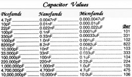
Just starting out? Perhaps this chart is helpful.
Yes I am and yes it is. The bar markings were previously undecipherable to me.
Thank you.
- Status
- This old topic is closed. If you want to reopen this topic, contact a moderator using the "Report Post" button.
- Home
- Amplifiers
- Chip Amps
- Help with first Power Supply for LM1875