Hi all,
My original attempts to get built a 3 channel cmoy may be found here - http://www.diyaudio.com/forums/showthread.php?s=&threadid=126152 - those designs never went anywhere, and I thought I ought to build one up on protoboard to check if the circuit worked in the first place. So I did, and it sat in the cupboard for months, waiting for me to wire in all the fiddly little jumper wires, because the layout was....not great.
But a few weeks ago, I finally got around to finishing it. And liked it. And then needed a gift, so it got boxed up properly and given away.
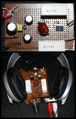
So, of course, I had to build up another version for the bench, and here's that version. For now, it uses OPA2132P and OPA227P, with the virtual ground provided by TLE2426. Power supply is a little bit overkill with 1000uF from V+ to V- (to be upgraded to 2200uF low ESR when I next go shopping for parts), with a 1uF polyester directly across the leads of the TLE (mostly because I had it sitting around with mangled leads, and couldn't think of something else to do with it! Not sure that it's actually doing anything of note), with the TLE being followed with low ESR 470uF caps between between the rails and ground. The OPA2132 is decoupled by the big 1.5uF greencap that's obscuring it in the photo.
I know I should also properly decouple the V+ and V- pins of each opamp to ground with about 0.1uF....but I don't have that value on hand at the moment. Since I have to buy them, should I use ceramics (they'd be X7R's, since that's what I can get), MKT's or polyprops?
The input caps are big, cheap 3.3uF greencaps - they'll do for this amp. Future upgrades, should I happen to feel like it, would see the opamps socketed, the OPA2132 swapped out for an OPA2107 (as used in the one I gave away - sounded fantastic), and the input caps upgraded to polypropylenes (probably Jantzen CrossCaps, since they're the cheapest I can get locally).
The next amp I build will probably be a crazy PIMETA clone using Russ White's Diamente discrete opamp stage as the output buffers.
My original attempts to get built a 3 channel cmoy may be found here - http://www.diyaudio.com/forums/showthread.php?s=&threadid=126152 - those designs never went anywhere, and I thought I ought to build one up on protoboard to check if the circuit worked in the first place. So I did, and it sat in the cupboard for months, waiting for me to wire in all the fiddly little jumper wires, because the layout was....not great.
But a few weeks ago, I finally got around to finishing it. And liked it. And then needed a gift, so it got boxed up properly and given away.
So, of course, I had to build up another version for the bench, and here's that version. For now, it uses OPA2132P and OPA227P, with the virtual ground provided by TLE2426. Power supply is a little bit overkill with 1000uF from V+ to V- (to be upgraded to 2200uF low ESR when I next go shopping for parts), with a 1uF polyester directly across the leads of the TLE (mostly because I had it sitting around with mangled leads, and couldn't think of something else to do with it! Not sure that it's actually doing anything of note), with the TLE being followed with low ESR 470uF caps between between the rails and ground. The OPA2132 is decoupled by the big 1.5uF greencap that's obscuring it in the photo.
I know I should also properly decouple the V+ and V- pins of each opamp to ground with about 0.1uF....but I don't have that value on hand at the moment. Since I have to buy them, should I use ceramics (they'd be X7R's, since that's what I can get), MKT's or polyprops?
The input caps are big, cheap 3.3uF greencaps - they'll do for this amp. Future upgrades, should I happen to feel like it, would see the opamps socketed, the OPA2132 swapped out for an OPA2107 (as used in the one I gave away - sounded fantastic), and the input caps upgraded to polypropylenes (probably Jantzen CrossCaps, since they're the cheapest I can get locally).
The next amp I build will probably be a crazy PIMETA clone using Russ White's Diamente discrete opamp stage as the output buffers.
Attachments
Cmoy with splitter of the voltage supply was built for use with one 9 V battery.
Result: +- 4.5 V with GND in middle
My question is: Who will force you to use one 9 V battery?
Alternative 1: Six 1.5 V batteries.
Result: +- 4.5 V with GND in middle
Added benefit:
1.5 Alkaline or NiMH 1.5 re-chargable has considerably higher energy
than 9 V (7.2) batteries.
Six 1.5 V batteries will work longer than one 9 V battery.
Alternative 2: Two 9 V batteries.
Result: +- 9 V with GND in middle
Benefit:
Some opamps will perform a bit better at higher voltage.
Some opamps even need more than 2x4.5 V to work.
===========================
Conclusion:
Before we decide for an amplifier, we are free to use any of the power sources that will fit our project.
To restrict our choice to something,
that needs extra devices to fix power supply voltage,
or that is less optimal in any other respect,
is not very good.
Result: +- 4.5 V with GND in middle
My question is: Who will force you to use one 9 V battery?
Alternative 1: Six 1.5 V batteries.
Result: +- 4.5 V with GND in middle
Added benefit:
1.5 Alkaline or NiMH 1.5 re-chargable has considerably higher energy
than 9 V (7.2) batteries.
Six 1.5 V batteries will work longer than one 9 V battery.
Alternative 2: Two 9 V batteries.
Result: +- 9 V with GND in middle
Benefit:
Some opamps will perform a bit better at higher voltage.
Some opamps even need more than 2x4.5 V to work.
===========================
Conclusion:
Before we decide for an amplifier, we are free to use any of the power sources that will fit our project.
To restrict our choice to something,
that needs extra devices to fix power supply voltage,
or that is less optimal in any other respect,
is not very good.
Power Supply foolishness
Foolish power supplying of Power Amps.
It is just as foolish as the often seen practice of using
only one fixed voltage source for for a power amplifier.
For both the voltage amplfication stage and the output follower stage.
The output stage heavy modulation current
will effect the input stages and the voltage amplification stage supply.
Additionally if not the voltage stage has higher voltage than output stage
voltage stage transistors will suffer from less dynamic headroom and even clipping.
Monkee see, monkee do.
This is sadly the general bad thinking when setting up a power amplifier design.
Guess they think they have to use 2 pins, like Op-Amps for the total power input.
Actually, for most low power preamp and opamps things are a bit different.
Due to the much less current transfered buy the output stage.
Remedy:
Power amplifier with output stage follower stage
should have at least two separate power supplies.
Output stage should separately supply heavy duty currents.
In order to reduce bad effects in input/VAS stages.
Attachment:
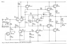
Foolish and wrong thinking Supply for 40 Watt power amplifier.
Would benefit from a separate transformer for the Output Follower.
Foolish power supplying of Power Amps.
It is just as foolish as the often seen practice of using
only one fixed voltage source for for a power amplifier.
For both the voltage amplfication stage and the output follower stage.
The output stage heavy modulation current
will effect the input stages and the voltage amplification stage supply.
Additionally if not the voltage stage has higher voltage than output stage
voltage stage transistors will suffer from less dynamic headroom and even clipping.
Monkee see, monkee do.
This is sadly the general bad thinking when setting up a power amplifier design.
Guess they think they have to use 2 pins, like Op-Amps for the total power input.
Actually, for most low power preamp and opamps things are a bit different.
Due to the much less current transfered buy the output stage.
Remedy:
Power amplifier with output stage follower stage
should have at least two separate power supplies.
Output stage should separately supply heavy duty currents.
In order to reduce bad effects in input/VAS stages.
Attachment:
Foolish and wrong thinking Supply for 40 Watt power amplifier.
Would benefit from a separate transformer for the Output Follower.
Attachments
Hi lineup - since you ask, I'm actually running it from a 24V switchmode plugpack. Why, you ask? Because it's a floating supply, so it doesn't matter how the source is grounded. I also use it with an 18V linear supply when the source isn't grounded.
I know that this setup is less than ideal, I know perfectly well how to build a proper dual rail power supply - but this option is cheap and easy, and is sufficient for its purpose. The next amplifier I build (the PIMETA clone) will be optimised for a stationary life next to the compute, and will probably have an LM338 based dual rail supply, as well as a nice clean 5V supply for an Alien DAC.
So, to summarise: yes, lineup, I know, but this amplifier is intended for use with a wallwart, so this is convenient.
Unfortunately, you're not even close.
You should be able to find an abundance of info on it but the 3rd channel is an active ground, its kinda like a poor man's balanced amp. You get some of the advantages of a balanced setup but without having to shell for a balanced source and re-wiring your 'phones.
Josh
You should be able to find an abundance of info on it but the 3rd channel is an active ground, its kinda like a poor man's balanced amp. You get some of the advantages of a balanced setup but without having to shell for a balanced source and re-wiring your 'phones.
Josh
While I might borrow the idea (oh, wait. It's already been done. Badly. Several times), more properly, it's an "active ground" cmoy - the same topology employed by the mini3, among others. I came across the idea in some very very old forum threads (about minimising offset errors in virtual ground cmoy's when driving low impedance headphones) and decided to give it a shot for myself, as a learning exercise.
I'm not a golden ear type. In my experience, including blind testing, essentially, most amplifiers sound the same, provided that harmonic distortion remains below 0.1% between 20-20,000hz, crossover distortion is minimal, input impedance is high enough to avoid unnecessarily loading the source, and output impedance is low. Oh, and provided the amp doesn't clip.
That is, used within their limits, amplifiers sound the same. In this case, the active ground topology minimises some of the limits inherent in un-buffered opamp based headphone amplifiers. The result is an amplifier that sounds good more of the time. Electrically, this appears to be due to avoiding excess current flow in the ground conductor.
All the above is, of course, just my opinion. Read up on the variations used in the PPA2, the m3, the B22. Active ground channels work in headphone amplifiers. I don't know why, really, but I know that I've evaluated the differences as scientifically as it's possible to without proper measurement equipment beyond a double blinded test using my ears. (in this case, it's easy to set up a jig to switch between the active ground and the ordinary ground rail).
Not having a go at you, pacificblue, just putting out some thoughts on the topic.
Nice job, you are ready for a PCB. Why don't you make one that is roomy enough so that you can make it work without stressing out too much? Then you can make another, smaller one.
I don't know what a "3 channel" CMoy is, seems like all you are doing is amplifying/buffering the virtual ground. Kind of like what a TLE 2426 would do but without the detriment of 30-50 mA current limit that the TLE can provide (assuming you use a high current opamp)-- but with the detriment of keeping the imprecise resistive divider at the input. I do not see how it approximates a balanced design in any way, but maybe I'm missing something (I looked at the hand-drawn circuit on the link).
I would not use the ceramics for your decoupling caps, but that's just me. My motto is if it works its great!
Oh, and put that baby in some kind of case!
Hi lgreen -
You're fairly well correct. I've actually used a TLE, which might make you wonder why I bothered - the real benefit seems to come from the fact that used this way, the input ground and headphone ground don't share a conductor, so the large return currents from the headphones can't cause voltage offsets in the ground conductor. This has been compared to the balanced "driving the headphones from both sides" approach, but isn't really all that similar.
The proper way of doing this is, as you say, to add a buffer for high current capacity. I plan to do that next, using a discrete opamp as a buffer with an output current capacity of about 150mA. I'm just waiting for the group buy for the PCB's of said discrete opamp to get rolling!
Hi Daveze,
If you poke around the Solid State section, you'll run across the thread for the Diamante. It's currently in prototyping, but there's been no issues reported, so a group buy for the PCB's will happen in the near future.
http://www.diyaudio.com/forums/showthread.php?s=&threadid=114632
There it is.
If you look closely, you'll notice that it does have ground connections....in the eyes of some, this disqualifies it from the status of "opamp", but there's plenty of uses for it.
(and, I've just realised, may or may not make it impossible for me to use in my intended application as a ground buffer.....thinking about it more, I think "not", but it'll look odd)
- Status
- This old topic is closed. If you want to reopen this topic, contact a moderator using the "Report Post" button.
- Home
- Amplifiers
- Chip Amps
- So, I finally built a 3 channel cmoy