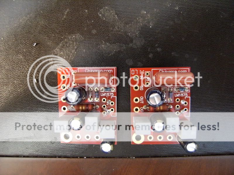
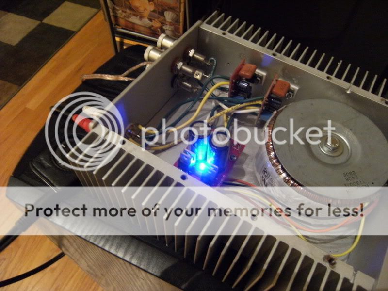
zymurgn said:I like the design of both ICs on the same heatsink, everything fits better. Aside from that, it is large enough be more than enough to dissipate the heat under full load. In other versions I might change it up though.
There's nothing wrong with that. My dual LM1875 amp (that I built about 15 years ago) has both chips on a 3"x1"x1" heatsink. I don't often drive it that hard, but when I do it doesn't get too hot. With moderate listening levels it is barely warm to the touch.
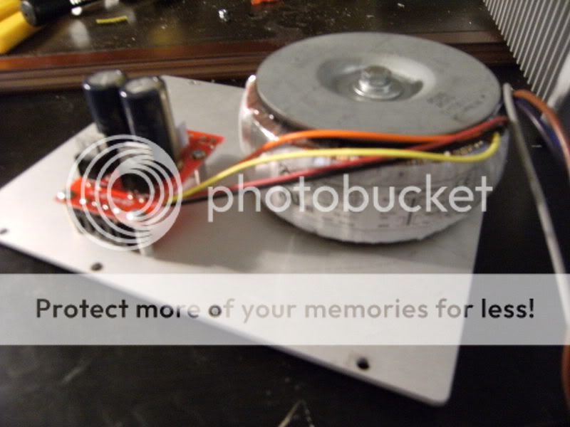
I am planning to use the XFM-D0012 toroidal transformer 21.5 Volts at 2.7 amps from Apex Junior for the LM1875 Gainclone Kit from BrianGT. On one side it has red,white,blue and black wires. On the other side it has orange, red ,brown and black wires.
Can someone please advise me the correct way to wire these to the kits power supply PCB and the mains connection?
Can someone please advise me the correct way to wire these to the kits power supply PCB and the mains connection?
How about asking the manufacturer or supplier for a connection diagram? The chances of getting it right by guessing are 24:1 against you and your amp, if I remember probability calculation correctly. And if you knew how to find out by measuring it, you would probably not be posting.vonfilm said:I am planning to use the XFM-D0012 toroidal transformer 21.5 Volts at 2.7 amps from Apex Junior for the LM1875 Gainclone Kit from BrianGT. On one side it has red,white,blue and black wires. On the other side it has orange, red ,brown and black wires.
Can someone please advise me the correct way to wire these to the kits power supply PCB and the mains connection?
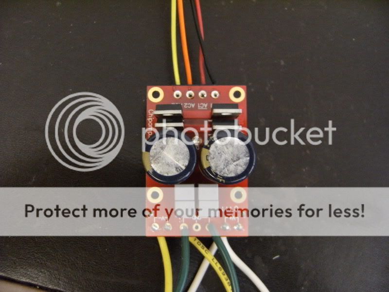
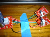
Looks correct. You should consider to drill the wires together for better noise immunity.vonfilm said:Here is my wiring between Power Supply and Amp boards:
pacificblue said:Looks correct. You should consider to drill the wires together for better noise immunity.
Many will twist the V+ and V- wires together around each other.
There is some benefit doing so, besides it looks better.
... maybe has got to do with wire inductance cancelling,
via the magnetic fields surrounding psu wires?
Twisting them together has two effects. One is that disturbances partly cancel each other out, because their direction in relation to the wires is constantly changing (or the other way round, if you like).
The other effect is that the same works the other way round. The magnetic fields produced around the twisted wires by the currents in them also cancel each other partly out, due to their constant change of direction relative to each other. The resulting effective magnetic field is weaker than that produced from two straight wires.
So twisting the wires makes them less prone to be disturbed and at the same time makes them less disturbing to their surroundings. Electromagnetically speaking that is.
The tighter you twist them together the more efficient are those effects. As usual you have to find the best compromise between twisting them as tightly as necessary and as loosely as possible. The reason is, because twisting wires means straining them and their connection points mechanically, and because it costs additional work and wirelength.
>I am planning to use the XFM-D0012 toroidal transformer 21.5 Volts at 2.7 amps
> from Apex Junior for the LM1875 Gainclone Kit from BrianGT.
> On one side it has red,white,blue and black wires.
Blue-Black and Red-White are two secondary windings, each rated 21.5V @ 2.7A.
> On the other side it has orange, red ,brown and black wires.
Orange-Red and Brown-Black are two primary windings. For 110V operation,
you will need to connect them in parallel to the AC. For 220V, connect in series.
See Nuuk's site if this info was not enough -
http://myweb.tiscali.co.uk/nuukspot/decdun/gaincloneFAQ.html
I believe this toroid was made by or for Adire, who are no longer in business. I acquired it from Apex Jr.
I found a thread where Slomatt used this particular transformer:
http://www.diyaudio.com/forums/showthread.php?threadid=115901
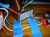
In it he connected the Orange/Brown and the Red/Black wires and connected them to the Mains
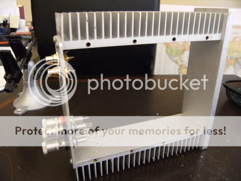
Looking at my IEC plug( see my picture) there are two terminals. One is marken N and the other L. Which pair should I connect to N and which to L?
I also have my secondary wiring wired as he described. Pacificblue said this looked correct.
I found a thread where Slomatt used this particular transformer:
http://www.diyaudio.com/forums/showthread.php?threadid=115901
In it he connected the Orange/Brown and the Red/Black wires and connected them to the Mains
Looking at my IEC plug( see my picture) there are two terminals. One is marken N and the other L. Which pair should I connect to N and which to L?
I also have my secondary wiring wired as he described. Pacificblue said this looked correct.
Pacificblue,
You are right. I was referring to what you said about the connection between PSU and Amp. My mistake.
My transformer appears identical to the one in Slomatts thread. You can see apicture from my link to his thread or at Apex Jr website.
I did use his description to wire the secondaries to the PSU. I have not soldered any of these connections yet because I want to be sure that the mains/transformer/PSU/Amp wiring is correct?
Can you tell I am new at this?")
You are right. I was referring to what you said about the connection between PSU and Amp. My mistake.
My transformer appears identical to the one in Slomatts thread. You can see apicture from my link to his thread or at Apex Jr website.
I did use his description to wire the secondaries to the PSU. I have not soldered any of these connections yet because I want to be sure that the mains/transformer/PSU/Amp wiring is correct?
Can you tell I am new at this?
- Status
- This old topic is closed. If you want to reopen this topic, contact a moderator using the "Report Post" button.
- Home
- Amplifiers
- Chip Amps
- My chipamp