Yes, I mentioned driver chip. Seems like it could also be used for an extra nice MyRef, and much easier to implement than parallel chip amps. I wonder why people have worked so hard on the MyRef series and still haven't upgraded the project to a high quality driver chip with high end outputs?Nobody mentionned LME498XX chips + discrete outputs. A choice i prefer when some power is required compared to paralleling plain chipamps.
Last edited:
Here you go: Project 115 - GainCloneThanks! That is really great! Got an example? Maybe a schematic?
Though it's actually over the pre amp. My memory is poor.
C5 is once again far too small in comparison to C1.Here you go: Project 115 - GainClone............
Classic and repeated all over the web.
Sure, and plenty else. If you're jumping in, then the discussion here is about the DIP switching, but placed in the NFB of the power chip, to tune gain resistors. The rest you can take or leave.C5 is once again far too small in comparison to C1.
Classic and repeated all over the web.
danielwritesbac View Post
Thanks! That is really great! Got an example? Maybe a schematic?
C5 is once again far too small in comparison to C1.
Classic and repeated all over the web.
the discussion is somewhat off topic but does try to address the issue ot trying to get the best performance from the chipamp.Sure, and plenty else. If you're jumping in, then the discussion here is about the DIP switching, but placed in the NFB of the power chip, to tune gain resistors. The rest you can take or leave.
That schematic that you linked falls at the first hurdle.
from Daniel's preceding post.220u (or more) for NFB cap
using the typical NFB resistor values he has suggested.
22uF does not get near.
Well, do it.
TDA7294 non-inverting amp:
Pair 220u amplifier board power caps and a single 2u polyester rail to rail.
47u (or 68u) for bootstrap
10k for input load resistor
10k for mute (no cap)
22k with 10u timer for standby
60k (120k||120k) for feedback resistor
2.7k for feedback-shunt resistor
220u (or more) for NFB cap
1u (or less!) for input
Output zobel is 10n with ~8R
Add RF filtering to input cap
Use a stiff power supply (20,000u per rail, 3a per chip)
Use less voltage than max (under-volt)
I have done a lot, may be more than anybody else. I cannot see anything there that I haven't tried. But may be on the high feedback resistance I have missed the 60k/2k7 combination.
I'll do this one tomorrow (being ill right now). Thanks.
BTW, when I said I couldn't make a TDA7294 to sound good enough, I haven't found a schematic that I think will blow away any other schematics from the LM overture series. There have been many blind tests since the popularity of Gainclone, and TDA7294 never won against the overture series (3876/3875/3886). If that will make the statement less subjective.
Last edited:

Sort your source and remove the buffers from the front end of the chipamp.
You've already got an op-amp. Why stack another for quality reduction? The LM1875's gain capacity goes high enough to clip itself even if driven by an MP3 player. Sufficient gain capacity is one of the conveniences of the 25 watt amplifier, and there's no need of a preamp to increase the clipping.")
However, if you've got the unavoidable urge to stack another op-amp in front of the power op-amp.
Actually I don't use buffer. It has gain but lower than usual. From practice I observe that the input gain stage is required to sound good.
Options are: high gain power amp, or low gain power amp plus additional input gain stage. I found it was better to set the gain of the power amp lower to lower noise and distortion.
Lme 49830 is for mosfets outputs
See also lme48910
Speaker Amplifier and Modulator - Mid/High-Power Amplifier - LME49810 - TI.com
lme49811
http://www.ti.com/product/lme49811
See also lme48910
Speaker Amplifier and Modulator - Mid/High-Power Amplifier - LME49810 - TI.com
lme49811
http://www.ti.com/product/lme49811
Last edited:
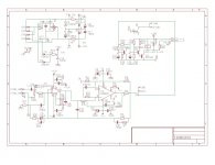
Just to make sure I'm close to understanding, Will someone download the photo zip, do some elementary hen scratching showing where the driver chip and/or PCB would be placed and post it here. Not looking for a schematic - just a point of reference or insertion. The photo is one of many MyRef mods floating around.
Attachments
Last edited:
Probably want to use a higher voltage for the LM3886. The LM318 is usable, but you may want to use something with less noise, say a NE5534A, change the compensation as well, if you change the OPAMP. Not sure about putting the OPAMP in the NFB loop with the LM3386, what is the advantage of that?
Rick
Rick
LM3886 and other Overture series contain the Spike system which exacerbates clipping and indeed sounds like a hard clipper to me. This is unkind to outputs and worsens the situation with a slight bit of sticking. Whatever the case may be, just imagine the worst outputs ever. Now, if you enclose this noisy TV power amp chip inside the feedback loop of a small signal op amp (nesting), then the problem is decreased by same proportion of the new global loop. That's automated quality control.Probably want to use a higher voltage for the LM3886. The LM318 is usable, but you may want to use something with less noise, say a NE5534A, change the compensation as well, if you change the OPAMP. Not sure about putting the OPAMP in the NFB loop with the LM3386, what is the advantage of that?
Rick
Short answer: Noise reduction (since it is actually predictable, more accurate term is "distortion reduction").
P.S.
The small signal op-amp in this case is run on regs, and the "clean reference" effect is copied to the entire amp via feedback. A similar approach with a discrete amp is to run the input+predrive (or driver chip) on regs or capmulti.
Last edited:
The TDA7294 circuit? Yes, it has been in service for several years.Thanks for your explanation, Daniel. You certainly have more experience than I using these parts. Has the posted ckt has been built and tested?
AndrewT helped me set the feedback shunt to correct values for good bass.
The clean form is posted; however, mine is accessorized. . .
I have added the blarebuster accessory to relax female voice for which I have a hearing peak and have added an "unnecessary output cap" accessory (progressive current drive like the JLH) for helping my sealed box speakers at lowest bass, for which I have a hearing dip. I didn't post the accessories because our ears, speakers, rooms and preferences are all different.
With a starting point of a neutral and clean amplifier, it was then inexpensive, and successful to accessorize it.
I think that it gives a unique feature of a chip amp that is pleasant at full blast.
I've got some opinions and observations on these differences.BTW, when I said I couldn't make a TDA7294 to sound good enough, I haven't found a schematic that I think will blow away any other schematics from the LM overture series. There have been many blind tests since the popularity of Gainclone, and TDA7294 never won against the overture series (3876/3875/3886). If that will make the statement less subjective.
SPL preference versus limiter sound:
To me, the difference can be totally explained by limiter type versus usage. With the spike and acutance effects, low volume playback with LM3886 will sound clearer than TDA7294; however, for high volume playback TDA7294's transparent soft limiter won't make you fatigued. So, opinions on quality could differ by SPL preferences. You can use TDA7294 to shove those difficult and/or inefficient speakers. The design that I posted earlier should be quite durable and cool running. For clearer mids at the cost of more forwards, see Mooly's post on "different compensation" and it *may* make TDA7294 sound more like LM3886, and I think that's unnecessary, but the choice is yours.
Power circuit:
1000u amp board caps for LM3886 means you want to stop the shout; however, 220u amp board caps for TDA7294 means you want to wake it up. That is a critical difference. Be sure to give TDA7294 a 220u on V+ a 220u on V- and a single 2u polyester from V+ to V- or else it won't stand a chance in competing with the clarity of a NatSemi overture series. Also, you need at least 5" (or more) of umbilical cable between power supply reservoir to amplifier board decoupling caps. Although LM3886's like all-in-one boards, the same will make TDA7294 go dull, so don't put the power supply on same board as amplifier--Op-amps are sensitive to power circuit and ideal support circuit for TDA7294 is much different than ideal support circuit for LM3886, so please avoid the expectations of rolling. I'm just trying to say that these chips have different needs.
Ebay Board:
If your TDA7294 kit has rectifier, power supply reservoir, and amp decoupling caps all on one board, and if the trace between power supply reservoir to amp decoupling caps is too short, the amp will sound helplessly dull. My unorthodox fix involves cutting the V+ and V- traces to disconnect the power supply reservoir caps from the amp decoupling caps, and then I bridge the cut traces with schottky diodes (or a resistor may work). This is "umbilical cable simulator" patch for dull integrated boards, whereby schottky and/or resistors have replaced the missing umbilical cable.
Of course, for an orthodox solution, we could upgrade the kit to Separate power supply and amplifier boards, and then the length of the umbilical cable (between the two boards) could be varied to whatever you like.
Needless to say, bargain quality tone controls on ebay kits need upgraded with a "tone cancel" switch so you can check out the sound of the amp without the influence of the tone section.
Prior to any fine tuning, we must have a clean head start, else there may be difficult component selection.
Last edited:
Oh. If you were asking about the LM3886 circuit at post 113, that's a MyRef.Has the posted ckt has been built and tested?
There are many of those in use.
Bob was asking how to upgrade the LM3886 circuit to LME498xx with high end outputs.
Last edited:
If this is true, then your gain stage could probably be moved to a better location, because I suspect your Source cannot adequately drive the cables.................. From practice I observe that the input gain stage is required to sound good.................
It's not the Power Amplifier that needs a buffer/gain stage, it's the Source that needs the gain stage/buffer.
That Source could be a vol pot, or a direct feed from an MP3 player, or DVD/CD player, or etc.
LM chip amps have a gain range. The 3886 is >10 and <50 (not sure of this number since I never approach it), but better performance is generally obtained with gain between 25 and 40.
take out IC2..........Will someone ............. do some elementary hen scratching showing where the driver chip and/or PCB would be placed and post it here................... just a point of reference or insertion. ................
Replace that with the Whole {driver chip and output stage and compensation} using the existing feeds from +IN, -IN, Vcc, Vdd, Output.
BUT, the MyRef has been developed around the 3886. There is compensation between the 3886 and the rest of the MyRef circuit.
That compensation will almost certainly need to be changed/adjusted to get stable performance from the assembly.
- Status
- This old topic is closed. If you want to reopen this topic, contact a moderator using the "Report Post" button.
- Home
- Amplifiers
- Chip Amps
- Which Chip AMP you like most?