So i honestly stolen this design from the www and made a layout.
No point in inventing the wheel again and again.
The layout is starting to look nice but i could always use a few more eyes to spot the erros.
Schematic.
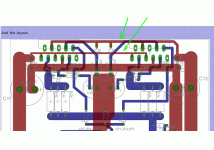
And the layout.
What say you all?")
/JZ
No point in inventing the wheel again and again.
The layout is starting to look nice but i could always use a few more eyes to spot the erros.
Schematic.
An externally hosted image should be here but it was not working when we last tested it.
And the layout.
An externally hosted image should be here but it was not working when we last tested it.
What say you all?
/JZ
How long is it between the rightmost 100nF decoupling cap and the leftmost power pin of the left hand chipamp?zei said:.....they are not that long, about 30mm between caps and screwterminals,.....
The other power pins are similarly crippled.
Do you really need parallel? Change to efficient 8ohm speakers.
What about the tolerance of the matching components to allow parallel to work correctly?
The decoupling can be tacked on the bottom afterwards if needed. I see the power leads are very thin and this goes against the idea of these paralleled to handle more current.
Running between the pins on the footprint of the LM doesn't give much room. Better to move these in order to make them wider.
Running between the pins on the footprint of the LM doesn't give much room. Better to move these in order to make them wider.
Attachments
- Status
- This old topic is closed. If you want to reopen this topic, contact a moderator using the "Report Post" button.
- Home
- Amplifiers
- Chip Amps
- Parallel LM3886 Chipamp layout (PA100)