hey this is my first post so im sorry about its crudness ")
ive been repairing 1970s powered advents for awhile now and recently one of mine broke again. so i decided to try and build some chipamps for them.
with the help of Randy M Rubin "rmrubin@gmail.com" i built these amplifiers.
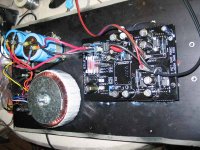
i used a 500VA 25+25 toroid with a 50A fairchild bridge and two mallory 24,000uf 50v caps. and lets not forget the relay rated for a 25A inductive load
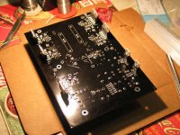
the board is 1.6mm with 2oz copper and black solder mask.
the tweeter amplifier is just a single LM3886 configured for 50W output into an 8 ohm load. the woofer amp is an almost exact copy of the BPA-200 servos and all.
a quick test showed it was flat from 20Hz to 100KHz, i didnt try below 20Hz.
i have 1 volt of ripple on each rail at full output, and 30-60mv of dc offset on the tweeter amplifier depending on temp\load. and between .5mv and 1mv on the woofer amp at all times
these bolt down to the orignal back plate of the powered advent, and will have 1"x1" aluminum bars milled smooth and bolted down to bolt the LM3886's too to sink them to the backpanel which is 90 degrees to them. sorry they arnt installed in the pictures, i had small 1"x1" heatsinks for quick testing and tweaking.
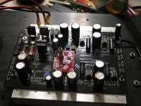
the new crossovers are 1.6mm 2oz copper red boards, that bolt down on standoffs near the center of the board, they are a 12db \ octave linkwitz riley designed to match the natural rolloff of the drivers, i also have a second 24db / octave one incase i want to use the same board on another speaker. perfect for biamping anyting ive got the amplifiers were also made so i can use them without the crossovers all together. let me know what you think
christopher jensen
ive been repairing 1970s powered advents for awhile now and recently one of mine broke again. so i decided to try and build some chipamps for them.
with the help of Randy M Rubin "rmrubin@gmail.com" i built these amplifiers.
i used a 500VA 25+25 toroid with a 50A fairchild bridge and two mallory 24,000uf 50v caps. and lets not forget the relay rated for a 25A inductive load
the board is 1.6mm with 2oz copper and black solder mask.
the tweeter amplifier is just a single LM3886 configured for 50W output into an 8 ohm load. the woofer amp is an almost exact copy of the BPA-200 servos and all.
a quick test showed it was flat from 20Hz to 100KHz, i didnt try below 20Hz.
i have 1 volt of ripple on each rail at full output, and 30-60mv of dc offset on the tweeter amplifier depending on temp\load. and between .5mv and 1mv on the woofer amp at all times
these bolt down to the orignal back plate of the powered advent, and will have 1"x1" aluminum bars milled smooth and bolted down to bolt the LM3886's too to sink them to the backpanel which is 90 degrees to them. sorry they arnt installed in the pictures, i had small 1"x1" heatsinks for quick testing and tweaking.
the new crossovers are 1.6mm 2oz copper red boards, that bolt down on standoffs near the center of the board, they are a 12db \ octave linkwitz riley designed to match the natural rolloff of the drivers, i also have a second 24db / octave one incase i want to use the same board on another speaker. perfect for biamping anyting ive got
the amplifiers were also made so i can use them without the crossovers all together. let me know what you thinkchristopher jensen
i have 1 volt of ripple on each rail at full output
how much current/total power drawn from supply at 'full output' ?
because 1 Volt RMS 120 Hertz ripple
can be made lower .. if you want to .. and think that you need it
1. just add two more rather big caps (say 2200/4700uF) at the LM3886 boards
that is, rather close to chip(s)
2. eventually put in 0.1 Ohm filter resistors (power resistors!)
.. in the wire in series right after your big blue caps
Otherwise
Congratuations to a great Audio Sound System.
And a good posted description, too.
thanks & regards
Lineup
okay
You already have those 1000 uF. Good!
And of course, what counts is the RIPPLE at CHIP supply pins.
What CHIP 'can see' is only what is right next to the PINS.
-----------
Now, the resistor.
Why not only use:
CAP24000uF - WIRE - CAP1000uF
Why use:
CAP24000uF - 0.1 Ohm + WIRE - CAP1000uF
Because the wire alone has not very high resistance+inductance.
Especially if wire is THICK, like Loudspeaker cable for example.
Not high impedance compared to one RESISTOR 0.1 Ohm ( 5w/10watt power resistor ).
To make an effective FILTER, we can not use Cap alone.
Cap together with some resistance makes one FILTER.
So called RC filter.
In this case the two caps + some resistance between form one
C - R - C filtering of your supply.
These are very effective filters, but not if the resistance component is too low.
By adding some little resistance, we will reduce ripple a bit.
It would be interesting if you measure Ripple BEFORE and AFTER adding resistor.
So you can see if I was really right ... or not.
Lineup
You already have those 1000 uF. Good!
And of course, what counts is the RIPPLE at CHIP supply pins.
What CHIP 'can see' is only what is right next to the PINS.
-----------
Now, the resistor.
Why not only use:
CAP24000uF - WIRE - CAP1000uF
Why use:
CAP24000uF - 0.1 Ohm + WIRE - CAP1000uF
Because the wire alone has not very high resistance+inductance.
Especially if wire is THICK, like Loudspeaker cable for example.
Not high impedance compared to one RESISTOR 0.1 Ohm ( 5w/10watt power resistor ).
To make an effective FILTER, we can not use Cap alone.
Cap together with some resistance makes one FILTER.
So called RC filter.
In this case the two caps + some resistance between form one
C - R - C filtering of your supply.
These are very effective filters, but not if the resistance component is too low.
By adding some little resistance, we will reduce ripple a bit.
It would be interesting if you measure Ripple BEFORE and AFTER adding resistor.
So you can see if I was really right
... or not.Lineup
you know, the main thing i wish i could improve but dont know how is the dc offset on the small amplifier. its just a single lm3886 with a standard non-inverting circuit, 21 gain using a 20k and a 1k resistor in feedback, and i have a 20k pot on the input. and of course a 1k resistor in series with the + input and a large coupling capacitor at the very begging. if i turn the pot all the way down grounding the input of the lm3886, i have an offset of 16mv. if i turn it all the way up, leaving only 20K resistance to ground on the input, i end up with between 40 and 60mv depending on temperture and such. is there any easy way to improve this?
im only concerned because i plan on this directly driving my tweeters. and its alittle on the highside
im only concerned because i plan on this directly driving my tweeters. and its alittle on the highside
wife wont let you have money
to buy necessary things
You have to talk some sense into that woman!
Does she want one happy husband ... or a sad one
By the answer to this question, you will know
if she really still loves you
or not ...
(show her this post .. and we see what happens)
Regards
Lineup - happily un-married & sharing life with his amplifiers
.. instead
bego2. i designed them with the help of Randy M Rubin.
there are no other boards other then a few he kept and the ones i have. i may consider selling some if your interested?
keep in mind, most of the amp is the BPA-200 with servos but the other small part is a 50w single LM3886. and theres probably other boards out there that are far easier to mount. mine have the chips UNDER the board facing outward.
thetube0a3 said:lineup : now that you saw what the amp actaully looks like what do you think of it? its my first amp.
I'm not lineup, but I think it looks quite good. Have spares you want to sell? PCB's that is, not assembled units.
For a "first" amp that is very nice. For a tenth amp that is STILL very nice.
Wife won't let you buy any parts!!!
 JOKING!!!
i do have extras but honestly id have no idea what to charge.
the 200W part worked perfectly right off.
while the single lm3886 has needed tweaking, so theres 2 empty sets of pads, and 2 sets of jumpered pads.. and the part i hate right now. the 2.2uf cap stuffed in with a 1k resistor in the feedback loop to get rid of the offset so i could direct couple to my tweeters.
ill take some pictures when its totally done. would you want crossoverboards also? or just amplifier boards?
i have the 12db LR and the 24db LR, but the amplifiers can be operated without them.
thetube0a3 said:bego2. i designed them with the help of Randy M Rubin.
there are no other boards other then a few he kept and the ones i have. i may consider selling some if your interested?
keep in mind, most of the amp is the BPA-200 with servos but the other small part is a 50w single LM3886. and theres probably other boards out there that are far easier to mount. mine have the chips UNDER the board facing outward.
ok. well i cant find any other shematic with layout...what price and would be a problem, i`m in croatia?
finally both speakers are almost finished. both are in daily use. the only thing left is i need to buy some fiberglass insulation to stuff them with. on the bench at clipping the rear panel got plenty warm yet the chips didnt get too hot. so im happy about that, everything tested perfectly in the end. out of everyting the hardest part was getting the bars of aluminum milled, drilled and counter bored.
here are some pictures, from both before the new amplifiers and after. one picture shows after i rebuilt one of the orignal amplifiers and had the cabinet full of polyfill, this didnt last long as i learned it was flammable and removed it immidiately. the amplifier in the picture is still working to this day, i sold it to someone online.
anywho let me know what you think
http://picasaweb.google.com/thetube0a3/EV?authkey=fUii9BtmX3w#
I know it's an old thread....
But I just wanted to say Helluva Job! That is a gold plated solution to the problem and I do mean that in the most complimentary way!
Now if you could make some more of those PC boards.....
Thanks for the compliment!
I have quite a few PCBs left over and have considered selling them cheap if anyone is interested. Just keep in mind its almost all SMD.
- Status
- This old topic is closed. If you want to reopen this topic, contact a moderator using the "Report Post" button.
- Home
- Amplifiers
- Chip Amps
- new amplifier for 1970s powered advents