Hi guys-I have an issue that came out of debugging & resolving ground loop noise for my chip amp-based car amplifier.
My modular chip amps (LM3886 PA100 design, taken from the National Semiconductor design examples) work and sound great, but when I experimented with using a ground loop isolator on the inputs of 2 channels, they went wild and produced noise and also popped the fuse of my power supply.
I would've thought this would be simple to resolve, but I can't figure out what causes this. The amps are built on my own custom PCBs with all required capacitance, .1% resistors (where applicable) and so on.
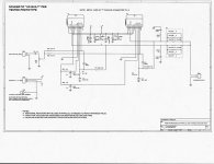
Also tried the suggestion of paralleling Rin with a small capacitance (100pF). but same result. Can anyone help? Actual schematic is below.
Thanks!
My modular chip amps (LM3886 PA100 design, taken from the National Semiconductor design examples) work and sound great, but when I experimented with using a ground loop isolator on the inputs of 2 channels, they went wild and produced noise and also popped the fuse of my power supply.
I would've thought this would be simple to resolve, but I can't figure out what causes this. The amps are built on my own custom PCBs with all required capacitance, .1% resistors (where applicable) and so on.
Also tried the suggestion of paralleling Rin with a small capacitance (100pF). but same result. Can anyone help? Actual schematic is below.
Thanks!
Attachments
It's a stereo pair RCA in, RCA out (isolated channels) by the reputable car accessory manufacturer, Stinger. Unfortunately I don't know the inductance but did open it up to see two 1:1 transformers, as expected.
It's not shown in the schematic as it wasn't originally necessary but quite helpful for testing/ground loop debugging.
It's not shown in the schematic as it wasn't originally necessary but quite helpful for testing/ground loop debugging.
Forgot to ask: is the system connected to chassis ground as well? I mean car chassis ground, not the amplifier chassis.
You may want to look at how the entire signal is being transmitted, including ground. I have a feeling your isolator is creating a ground loop instead of lifting it, and forming a resonant circuit of some sort.
Can't understand why I can't edit my posts anymore to add more info.
You may want to look at how the entire signal is being transmitted, including ground. I have a feeling your isolator is creating a ground loop instead of lifting it, and forming a resonant circuit of some sort.
Can't understand why I can't edit my posts anymore
to add more info.Hi, & thanks for the replies. Yes, the input capacitor is present at all times (it's on the PCB) and yes the input resistor setting (potentiometer) does not seem to alleviate the issue.
The design is not connected to chassis ground (LM3886 amp modules & power supplies are isolated to prevent the ground loops).
After looking further, I just noticed that in other data sheets National Semi. design examples show a slightly different design, with: 1. input potentiometer, connected to: 2. input capacitor, then 3. another (47K) resistor to ground, before the 1K resistors that go to the +audio pins.
I wonder if that would affect it?
The transformer coil and Cin form a loop through Rin. They may be forming an oscillator. You may try to take Cin out (or jumper it) and see, if the problem persists. A transformer cannot have DC at the secondaries, so Cin is probably not necessary, when running with the transformer.
Maybe you also take out those two 200pF capacitors across the inputs for the test. I cannot read their names in the schematic. Cn1 and 2 or Cu 1 and 2?
Maybe you also take out those two 200pF capacitors across the inputs for the test. I cannot read their names in the schematic. Cn1 and 2 or Cu 1 and 2?
Hi Pacificblue-those 200pF caps are "Cc1", "Cc2".
I'll try again removing Cin and testing with the G.L.I. on the inputs of 2 amp modules, along with removing CcX (200pF) on those LM3886 inputs.
Thanks for the ideas! I was thinking of all places, surely someone here has enough amp (and chip amp especially) experience to have seen something at least similar to my problem before.
- Status
- This old topic is closed. If you want to reopen this topic, contact a moderator using the "Report Post" button.
- Home
- Amplifiers
- Chip Amps
- LM3886 Amp Oscillating When Ground Loop Isolators Are Used (?)