Fellow DIYer,
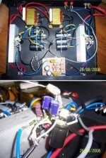
My LM3876TF gainclone is my latest GC project and I'm using point to point approach based on the LM3876 datasheet, with additional zobel network at the output..
I'm confused now since it 'producing' minus 5 to 7 volts DC at the speaker output on both channels
First time I powered the unit, I was having minus 25 to 27 volts DC at the output... then I decided to connect pin no. 5 (V+) to pin no. 1 (V+) , strangely the voltage at the output dropped to minus 5 to 7 volts DC...
The supply for both chips are ± 30 VDC
I checked and re-checked all of the component connections to the chip's pins... still I got the negative or minus VDC at the output.
Would appreciate any help from friends here...
Pictures as per attached
Attachments
Thanks for the responses...
Hi Andrew,
I'm using LM3876TF and although it is already insulated I also used mica washer to attach the chip to the heatsink. Is there any method to confirm that the chip is "electrically insulated" by using multimeter, e.g. what pins to check?
I'm using the LM3886 schematic as attached.
Hi Sangram, I didn't use additional resistors on the input pin to ground. I'll try this!!
Attachments
Take that washer out. The TF package is already electrically insulated. The washer worsens the thermal conduction to the heatsink and is therefore counterproductive.Dino-Indo said:I'm using LM3876TF and although it is already insulated I also used mica washer to attach the chip to the heatsink.
Hi,
the Zin setting resistor is missing from that schematic.
The output Zobel is missing.
The DC blocking capacitor on the input is missing.
The RF attenuation capacitor (filter) on the input is missing.
Most of these (and the TF) are mentioned in various locations in the datasheet.
Also mentioned is the pin to backplate connection.
Read the datasheet.
He's using a pot so technically he's got the Zin resistor, though it's variable it should not cause DC offset of that order. I'm willing to be corrected on that one.
Also it's the TF package, so no insulation is required. It's automatically insulated from the heatsink.
And I've stopped putting Zobels on amps I build for myself (though I always include it when I build one for a friend). And the TS did mention he added a Zobel even if it isn't there in the schema - but it's not related to offset either. And I never put in the filter cap between the inputs either.
The missing Cin looks to be like the most likely culprit, maybe there's DC coming in from the source.
Hi All!!
Finally, my LM3876TF gainclone is up and running!! Last weekend, I decided to dismantle all the connections and follow the schematic as per datasheet ... redoing the solders and now it worked!!
Comparing LM3876 to LM3886 gainclone my first impression after 1 hour comparing them, is the difference of the sound, where LM3886 tends to be more 'punchy' on the midrange to low, whereas LM3876 is more cleaner and clearer on the midrange to high frequency.. but off course, all depends on various aspect (e.g. the components used, PSU design etc: My LM3886 is using single toroid 5A 300 VA, where my LM3876 is using dual EI trafo 3A)
Again.. many thanks for your help, advices and suggestions !!
with Best Regards,
Dino
PS: Too bad I didn't have a chance to implement Mr. Nelson Pass' buffer preamp B1 on it.. I need to check and recheck all of my point-to-point approach on his buffer design....
Nelson Pass B1 Buffer Preamp ROCKS!!
Dear All,
Finally my Gainclone LM3876TF sing with Mr. Nelson Pass B1 Buffer Preamp circuit!!
It rocks!! And I believe the circuit does 'boost' the LM3876's performance!!
Kudos to Mr Pass for his design!!
And many many thanks for sharing the schematic & comprehensive but simple explanation on your web site!!
Best regards from Indonesia!
- Status
- This old topic is closed. If you want to reopen this topic, contact a moderator using the "Report Post" button.
- Home
- Amplifiers
- Chip Amps
- LM3876TF: minus 5 to 7 volt DC at the output