Yes, a single supply needs two rails, one positive and one negative, where the negative is usually at the same time the ground. A split supply has three rails, positive, negative and ground, where the ground potential is in between positive and negative.
The basic differences are usually that you
Depending on the chip amp IC you use, some of those components may already be built-in. You need to read the corresponding datasheet. Usually there is a schematic of how the IC you use must be implemented with a single supply.
- need a virtual ground between the positive rail and the real ground, to which the input signal is referenced. That means usually three more resistors and two more capacitors. An additional transistor or even op amp is sometimes used to improve the stability of that virtual ground.
- need a (big) DC blocking capacitor between the amp output and the speaker. The virtual ground is present at the amp output and the resulting DC signal at half the rail voltage could destroy the connected speakers without that capacitor.
Thank you very much for your detailed answer, it cleared up several questions.
I was mistaken about the power supply.
It is a center tap transformer, that shows (after rectification):
55+ 0 55-
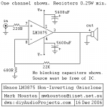
I have tied the 0 to ground (chassis). I'm building the LM3875 amp, but I am only using this same supply for both channels. From what I gather you said, I in fact have a split supply I believe.
I'm using this schematic by the way.
Thank you for your help, I believe I now understand how to go about it...
Attachments
Don't use +-55Vdc to power any of the National chipamps.
National do the LME498xx series that can be powered from +-55Vdc and even higher.
Are you new to chipamps and simple electronics? If so then don't build that example schematic.
All the optional components to improve reliability have been omitted. This example should only be built by experienced builders who know how the circuit works and how to check it is working properly and know the risks they run if adopted as shown.
Don't use +-55Vdc to power any of the National chipamps. National do the LME498xx series that can be powered from +-55Vdc and even higher.
Are you new to chipamps and simple electronics? If so then don't build that example schematic.
All the optional components to improve reliability have been omitted. This example should only be built by experienced builders who know how the circuit works and how to check it is working properly and know the risks they run if adopted as shown.
There are several things wrong with building from that schemo ...

One might hope that AndrewT would offer something a bit more reliable / cleaner / practical ... Thanks AT
I hope the kit designer/supplier comes in with an opinion.
Thanks Andrew, Simple yet sound advice. It makes sense that what will work for one amp design may not work for another. I have found some other threads that feature Peter Daniel, and I am zeroing in on what I want to do.
Thanks Pacific Blue, very informative post. I am going with the "stardard" PSU as this is my first one!
I was not too keen on these Disadvantages either:
May show serious HF instability problems, either alone or in combination with the amplifiers powered. The regulator output impedance is likely to rise with frequency, and this can give rise to some really unpleasant sorts of HF instability. Some of my worst amplifier experiences have involved (very) conditional stability in such amplifiers.
The amplifier can no longer deliver higher power on transient peaks.
The overall power dissipation for a given output is considerably increased, due to the minimum voltage drop through the regulator system.
The response to transient current demands is likely to be slow, affecting slewing behavior.
Like everything in DIY, take the good with the bad!
Allen
First amp, suitable transformer?
Hi all!
I was at the local junkyard and salvaged an old pioneer amplifier to check if it contained any useful stuff for my first lm3886 build.
Found a neat little transformer (weighs about 1,7kg which should be around three pounds).
I fired up the amplifer, turned it upside down and started measuring.
Between the secondaries marked 7-8-9 I got 22,8v when I measured 7-8 and 8-9.
I followed these leads to their fuses and they were 3,15A. Can or will this be "ok" for a stereo pair of lm3886? I do not know the VA rating of this transformer, it is probably not all that high.
I am planning on using at least 10000uf per channel in the powersupply, "snubbersupply".
Anyone with experience of this, is it better to use less or more?
I have read about others using 80VA toroids for a stereo amp, but of course they have been limited when it comes to output power.
Thanks in advance for any thoughts.
Attachments
Last edited:


The findings indicate a 120 VA transformer and the voltage appears to be a nominal 2x20 V. That is comfortable for 8 Ohm speakers. It is pushing it a bit for 4 Ohm speakers, but with generous heatsinking it is worth a try.
Snubbers in the power supply don't make much sense to me.
Snubbers in the power supply don't make much sense to me.
The findings indicate a 120 VA transformer and the voltage appears to be a nominal 2x20 V. That is comfortable for 8 Ohm speakers. ...
Your comfort zone may be different than mine ...
... Snubbers in the power supply don't make much sense to me.
Your comfort zone may be different than mine ... I like to see the power supply noise floor down at least -110 db = snubbers help.
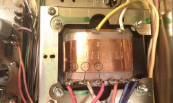
that looks like a gauss band around the transformer winding. An indication that they have spent a bit of money on trying to improve the performance standard of the transformer.
Are those the mains connections exposed on the bottom side?
In their present exposed condition they could be accidentally shorted to each other or to core. Take care.
Are those the mains connections exposed on the bottom side?
In their present exposed condition they could be accidentally shorted to each other or to core. Take care.
AndrewT: Yes, both the primary and secondary connections are exposed, they were mounted facing the bottom of the amp. I am thinking of mounting it upside down so that the connections are easilly accessible. I will most likely put it upside down so that the connecions are easy to access.
Or we may be talking about different aspects of comfort. E.g. you may be uncomfortable with so little power, while I am comfortable, because the supply voltage leaves safety margins in the IC's voltage rating and heatsinking.Your comfort zone may be different than mine ...
Liking to see -110 dB is a personal preference, not an objective necessity, but that is absolutely OK if you have such ambitions. Or if your speakers are so revealing and you live somewhere remote, where no ambient noise covers anything below -70 to -80 dB anyhow.Your comfort zone may be different than mine ... I like to see the power supply noise floor down at least -110 db = snubbers help.
What I fail to see is, how those snubbers should bring the noise floor in the audio band significantly down. The caps in that "Snubberised PSU" are so small, they only work far above the audio band, if at all. And resistors don't remove noise, but add their own. What makes it worse is that those snubbers are in the wrong place to do any good.
You want to bring power supply noise down? Add 10-100 nF capacitors next to the rectifiers to fight diode switching noise. Then add big smoothing caps to filter the AC components out, and that is where you really determine the power supply noise floor. Finally you need 10-100 nF decoupling caps next to the supply pins of all ICs and that's it.
You may still need a mains filter to achieve your ambitious goal, but the noise that comes in from mains does not really count as the power supply's own noise and will certainly not be impressed by snubbers.
Or we may be talking about different aspects of comfort. E.g. you may be uncomfortable with so little power, while I am comfortable, because the supply voltage leaves safety margins in the IC's voltage rating and heatsinking.
Granted, except that higher voltages give the designer the option of improving dynamic range and improving PS noise levels. (More volts and less current can result in the same power output, no?)
Liking to see -110 dB is a personal preference, not an objective necessity, but that is absolutely OK if you have such ambitions. Or if your speakers are so revealing and you live somewhere remote, where no ambient noise covers anything below -70 to -80 dB anyhow. ...
Well, a bit more than just personal preference. 16bit CD quality is in the 80+db dynamic range, so that benchmark might be your personal preference. Mine is 24bit or better DVD quality = 100db to 115db range.
Building to that quality thresh hold = more, better.
What I fail to see is, how those snubbers should bring the noise floor in the audio band significantly down. The caps in that "Snubberised PSU" are so small, they only work far above the audio band, if at all. And resistors don't remove noise, but add their own. What makes it worse is that those snubbers are in the wrong place to do any good.
Yes ... No ... Yes, maybe. Placing "snubbers" on the +/0/- power rails right next to the amp (or op-amps) is a recommended chip maker design (TI, National, Analog Devices, et al).
You want to bring power supply noise down? Add 10-100 nF capacitors next to the rectifiers to fight diode switching noise. ...
Mmmmm ... I do both, add plastic 10-100uF across the big PS electrolytic caps (both xformer and output rails) AND the same plastic caps across the power rails very, very close to the +/0/- power pins on the input gain stage of any amp I build.
Your results may vary, but I have come very close to (IMHOP) the ideal -110db PS noise floor = which compliments the 105-120db dynamic range of 24bit-48k/96k/192k of DVD audio track (and pro music recording studio quality).
---
"All of the world's problems can be fixed by resolving the impedance mis-matches ..." - Bob Porter / Mad Science
Last edited:
All very good advise ...
I haven't read through the document fully yet, and I won't be constructing my own PSU, but one quick question before I start wiring up my chip-amp. This is very basic and easy... Is it common practice to tie the PSU ground to earth ground at some point, or does it float internally? What about all the connectors that fit to a metal enclosure?All very good advise ...
- Home
- Amplifiers
- Chip Amps
- Chip amp power supply- a beginners guide