"How much capacitance do I use in the in the power supply?" its mentioned-----".....and 1000 uF on each pin of the chip amp. " please explain.
It means that capacitors of 1000uF value are soldered into the circuit as closely as possible to the (power supply) pins of the chip.
Again,.......is the '35A bridge' used in the chassis grounding same as the bridge used in the rectifier.
Yes, it is the same sort of item.
zinblade19 said:Hi Nuuk,
I intend to use two transformers for powering two amplifiers separately-------- all in the same chassis, can I connect the zero volt lines of both the psu thru te same 35A bridge to the chassis??
In that case I would connect the power ground stars of each channel together with a thick piece of wire and run a single wire from the middle of that wire to the safety earth circuit.
Thank you
Hi,
this email is just to thank you all and in particular Nuuk, for this great thread. I want to inform you that your efforts are really helpfull.
6 months ago I never did a solder my-self; now I built an integrated amp for my laptop based on the lm1875 chip and a PSU for a VSPS Phonoclone phono pre. They are both working great.
It was not possible without you... and now it is time for my new "reference amp" based on Peter's kit.
Thank you again
Renato
Advantage of one big transformer
One large transformer will cost less than two small ones for same capacity. Large transformers are more efficient. Simpler wiring. More power is available to the channel that needs it. Get a larger transformer than you need at the minimum voltage you need for your power and you will have better regulation and reduced heat.
One large transformer will cost less than two small ones for same capacity. Large transformers are more efficient. Simpler wiring. More power is available to the channel that needs it. Get a larger transformer than you need at the minimum voltage you need for your power and you will have better regulation and reduced heat.
Re: Advantage of one big transformer
Your last sentence contradicts the first. Using a single transformer you will have worse regulation since high output on one channel reduces the voltage available for the other, typically peaks occur on both channels somewhat simultaneously.
In some applications cheaper is good, but we aren't necessarily comparing apples:apples, many people may find surplus transformers or already have something they would use, or find a supplier with good prices but limited choices instead of paying full, premium price from an electronics house which tends to cost more for one large transformer than two not so much smaller ones from another source.
Ultimately if regulation is important enough, one spends the extra money for a power supply stage that drops it's output voltage below the max sag the input stage would ever see from peak load. In other words if an amp would drag transformer X down to 30V at peak output, instead use transformer Y which is high enough above 30V that no matter the load, the output of a regulation stage in a PSU stays at the 30V target.
This way, instead of trying to minimize PSU voltage depression at peak amp output, you are instead reducing peak voltage when there is light load. It is certainly less efficient, but if we cared most about efficiency we'd build Class D or at least use a switching PSU instead.
How fancy a regulation stage in a PSU is, depends on the other project goals and ability of the builder. Relatively speaking it need not be expensive, I recall CarlosFM made at least one that used LM338 which is good for up to 5A if properly heatsunk, and a pass transistor could be added to the reference circuit to get 10A or more, or even simplier if noise rejection isn't important to the builder would be a capacitance multiplier instead of LM338 or a zener/pass-transistor arrangement. All will effectively keep the power rails regulated much better than any reasonably sized transformer choice alone.
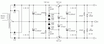
Since a capacitance multiplier is a simple concept and CarlosFM has posted various schematics of his LM338 implementation, I'll attach an example of a zener pass-transistor PSU, one that uses two zeners in series to get closer to a target voltage if a supply of zeners for the target aren't readily available (but if they were available then certainly one zener instead of two in series could be used instead).
It is an example only, to go to the trouble and then not make the next step to a true regulator IC doesn't seem logical unless someone were limited in budget and needed to use parts they already had to build something meaning the circuit topology might be similar even if the parts values were changed.
ted4412wilt said:One large transformer will cost less than two small ones for same capacity. Large transformers are more efficient. Simpler wiring. More power is available to the channel that needs it. Get a larger transformer than you need at the minimum voltage you need for your power and you will have better regulation and reduced heat.
Your last sentence contradicts the first. Using a single transformer you will have worse regulation since high output on one channel reduces the voltage available for the other, typically peaks occur on both channels somewhat simultaneously.
In some applications cheaper is good, but we aren't necessarily comparing apples:apples, many people may find surplus transformers or already have something they would use, or find a supplier with good prices but limited choices instead of paying full, premium price from an electronics house which tends to cost more for one large transformer than two not so much smaller ones from another source.
Ultimately if regulation is important enough, one spends the extra money for a power supply stage that drops it's output voltage below the max sag the input stage would ever see from peak load. In other words if an amp would drag transformer X down to 30V at peak output, instead use transformer Y which is high enough above 30V that no matter the load, the output of a regulation stage in a PSU stays at the 30V target.
This way, instead of trying to minimize PSU voltage depression at peak amp output, you are instead reducing peak voltage when there is light load. It is certainly less efficient, but if we cared most about efficiency we'd build Class D or at least use a switching PSU instead.
How fancy a regulation stage in a PSU is, depends on the other project goals and ability of the builder. Relatively speaking it need not be expensive, I recall CarlosFM made at least one that used LM338 which is good for up to 5A if properly heatsunk, and a pass transistor could be added to the reference circuit to get 10A or more, or even simplier if noise rejection isn't important to the builder would be a capacitance multiplier instead of LM338 or a zener/pass-transistor arrangement. All will effectively keep the power rails regulated much better than any reasonably sized transformer choice alone.
Since a capacitance multiplier is a simple concept and CarlosFM has posted various schematics of his LM338 implementation, I'll attach an example of a zener pass-transistor PSU, one that uses two zeners in series to get closer to a target voltage if a supply of zeners for the target aren't readily available (but if they were available then certainly one zener instead of two in series could be used instead).
It is an example only, to go to the trouble and then not make the next step to a true regulator IC doesn't seem logical unless someone were limited in budget and needed to use parts they already had to build something meaning the circuit topology might be similar even if the parts values were changed.
Attachments
Some experts say to use large bridge rectifiers instead of those little diodes. 400 V or more, 35 amp bridge should work great.
http://sound.westhost.com/power-supplies.htm#rectifiers
http://sound.westhost.com/power-supplies.htm#rectifiers
Re: ac to dc
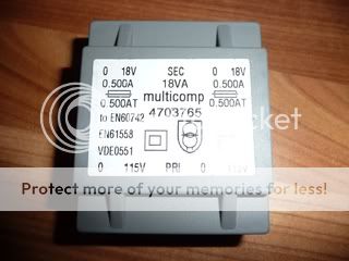
DAMN that is a HUGE transformer !! I'm guessing you got it really cheap (or free) somewhere? What does it weigh, about 50 pounds?
Anyway, you won't use close to even half of that amperage as long as this isn't any kind of crazy frankengainclone. So I'd say the MUR860's at 8 amps should be fine (after all, Nuuk suggests 3A as a good starting point in the article). Although with that big of a tranny, it'd probably be a good idea to put a thermistor such as a CL60 in series with one side of your primaries (in addition to the fuse, of course)
of course, as ted says, a 35A bridge will work fine too (I'd still use the CL60 though)
jamesjmcgee said:I was looking at the mur860 most use but its 8amp...being my transformer output has 2 taps, 16v @ a massive 27.5a each,
What would be the best diodes, or bridge rect. to use?
Thanks
James
DAMN that is a HUGE transformer
!! I'm guessing you got it really cheap (or free) somewhere? What does it weigh, about 50 pounds?Anyway, you won't use close to even half of that amperage as long as this isn't any kind of crazy frankengainclone. So I'd say the MUR860's at 8 amps should be fine (after all, Nuuk suggests 3A as a good starting point in the article). Although with that big of a tranny, it'd probably be a good idea to put a thermistor such as a CL60 in series with one side of your primaries (in addition to the fuse, of course)
of course, as ted says, a 35A bridge will work fine too (I'd still use the CL60 though)
Hi
I have just built a couple of adjustable regulated power supplies for a pair of Pedja's discrete buffers. I have read somewhere that I can put a low value resistor after a single reservoir capacitor to help filter the supply.
Can someone suggest a suitable value?
Thanks
Richard
I have just built a couple of adjustable regulated power supplies for a pair of Pedja's discrete buffers. I have read somewhere that I can put a low value resistor after a single reservoir capacitor to help filter the supply.
Can someone suggest a suitable value?
Thanks
Richard
Attachments
that creates a CRC filter.Tripmaster said:I have just built a couple of adjustable regulated power supplies for a pair of Pedja's discrete buffers. I have read somewhere that I can put a low value resistor after a single reservoir capacitor to help filter the supply.
Find your excess voltage when worst conditions apply.
That is the maximum voltage you can drop across the added R of the CRC. use a resistor combined with your output current that drops <=your excess voltage.
If your excess voltage at worst case conditions is very low or negative (i.e. dropout @ low mains voltage and maximum current draw) then R<=0r0.
andreja said:I have transformer with output of ~45 V and I want to use it to built an amplifier with tda1514 but I need symmetric power supply +-30V How to make a ground connector if I haven't one?
There was some talk about it here: http://www.diyaudio.com/forums/showthread.php?postid=1799612#post1799612
Hi
I purchased several 18vac encapsulated transformers a while ago as they were only 70p each! I have just come to use a pair of them and the output from both secondaries are 23vac. When I have measured other transformers in the past the voltage normally exceeds the stated amount by one or two volts.
Secondary output 23vac
Rectified 20.2vdc (not connected to power supply)
Rectified 30.7vdc (reading taken from power supply input)
I am using KBU8G rectifiers.
Any ideas?
Thanks
Richard
small transformers have much higher regulation that big transformers.
It not unusual for regulation to exceed 15% in the smaller sizes and even approach 30%.
23Vac is<28% regulation But I see you have a 230Vac transformer running on a 240Vac UK supply.
That takes off a further 4% giving <23% regulation.
This is all quite normal.
Now to specifics.
What is the mains input voltage when you measure the secondary open circuit output voltage?
That will let you calculate the turns ratios and the regulation.
Now add a 180r or 220r Power resistor to each secondary and repeat the voltage measurements.
Now add a second pair of 180r or 220r Power resistors in parallel to the first pair and repeat the measurements.
The output voltage should be getting close to what the manufacturer specified for a 230Vac mains supply.
AndrewT said:small transformers have much higher regulation that big transformers.
It not unusual for regulation to exceed 15% in the smaller sizes and even approach 30%.
23Vac is<28% regulation But I see you have a 230Vac transformer running on a 240Vac UK supply.
That takes off a further 4% giving <23% regulation.
This is all quite normal.
Now to specifics.
What is the mains input voltage when you measure the secondary open circuit output voltage?
That will let you calculate the turns ratios and the regulation.
Now add a 180r or 220r Power resistor to each secondary and repeat the voltage measurements.
Now add a second pair of 180r or 220r Power resistors in parallel to the first pair and repeat the measurements.
The output voltage should be getting close to what the manufacturer specified for a 230Vac mains supply.
Thanks Andrew
I don’t think I have any power resistors in stock at the moment (at the office whilst typing this) so I will call into Maplin at some point.
I have built a couple +&- power supplies using LM317T and 337T regulators. I am currently dropping 10.7vdc between input and output, this is then regulated again on a buffer from 20vdc to 15vdc using LM7815 and LM7915.
Will the LM317T - 337T run hot without a heatsink?
Thanks
Richard
Will the LM317T - 337T run hot without a heatsink?
Probably. I reckon you would be better to drop around 7.5 volts on both stages of regulation and then use small heatsinks to be on the safe side.
")
Nuuk said:
Probably. I reckon you would be better to drop around 7.5 volts on both stages of regulation and then use small heatsinks to be on the safe side.
Ok, thanks
I recently built a LM3886 gainclone amp and what I’ve noticed is that every circuit as a switch before the transformer. After testing and playing around with the amp I found that after switching the switch off the amp still runs for about 10 seconds drawing voltage from the caps. So everytime the amp is turned back on the caps would charge back up, does this but any stress on the caps and/or transformer? Is there a better solution to this like a relay between the psu and amp board because Id like to find a way to have the amp just turn off when the switch is turned off
Thanks
Thanks
- Home
- Amplifiers
- Chip Amps
- Chip amp power supply- a beginners guide