AndrewT said:
this is not right.
The bulb must be off when both switches are off.
The bulb must not flash, not even briefly nor dimly, when the ON switch is pressed and there is no load.
The bulb must go out, if it is already glowing or lit, when the bypass switch is pressed.
A big load would be a kettle, fan heater, iron, toaster etc.
Sorry Andrew I am an idiot (I can see you nodding your head!) It must be the late nights
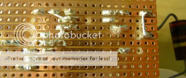
I am using these switches because it was all I could get at the time.
http://www.maplin.co.uk/module.aspx?moduleno=34858
1. The bulb does not light when when the switches are pressed
2. No load - Nothing connected to the IEC plug=Light does not flash.
It doesn't flash when I have the transformer and bridge rectifier connected.
3. Ive just plugged in my coffee machine and the light glows brightly and turns off when I press the bypass button.
The light bulb tester must be fine
")
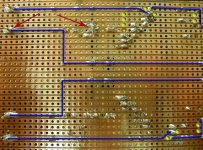
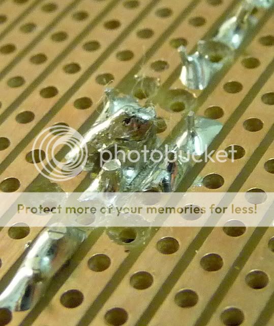
audio1st said:I hope this shows it better..
Thanks Barry
I will check this now and report back
the light bulb tester does not need any switches.
A basic tester is just a plug top to connect to the mains.
A bulb holder.
A socket outlet to send power to your project.
The switches are add ons for those that want to do further experimentation and be able to conveniently switch off.
We have switched wall socket outlets, or we can just pull the plug.
AndrewT said:the light bulb tester does not need any switches.
A basic tester is just a plug top to connect to the mains.
A bulb holder.
A socket outlet to send power to your project.
The switches are add ons for those that want to do further experimentation and be able to conveniently switch off.
We have switched wall socket outlets, or we can just pull the plug.
Progress!!!
I cut the various tracks and added links as Barry suggested and I now get a 24-25v output. (Thanks
)The bulb tester has come to my aid already, when I applied the power the bulb dimly glowed and it appears 'R2' 0.25w 130R resistor was over heating.
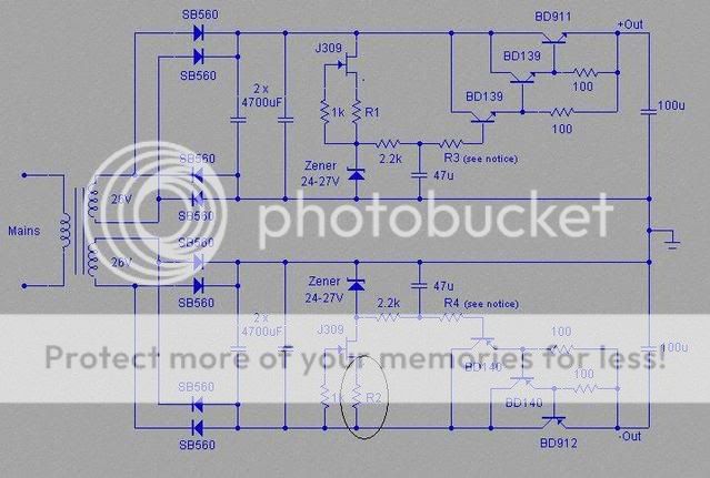
Should I change this for a 0.6w resistor or is it something more sinister?
R2 should only be passing a few mA.
It should run near cold. Id=8mA gives about 8mW of dissipation.
Check the voltage across R2.
Check the voltage across the Zener. Check the voltage Vds across the FET.
These should add up to the supply voltage. I suspect that either the Zener is back to front and/or the FET is damaged.
It should run near cold. Id=8mA gives about 8mW of dissipation.
Check the voltage across R2.
Check the voltage across the Zener. Check the voltage Vds across the FET.
These should add up to the supply voltage. I suspect that either the Zener is back to front and/or the FET is damaged.
mjf.mjf said:you can measure the voltage drop across r2,square it and divide it by 130 that gives you the power (probably around 0,3watt).
to get 300mW dissipation in R2 it must pass 48mA.
0.048^2 * 130 = 0.2995W and that would develop a Vgs of -6.24V.
How would you get 48mA through the series combination of Zener 24V + jFET + 130r?

audio1st said:Probably not related, but is the second BD140 the correct way round?
Good morning

Yes its the right way, just a different brand to the first
AndrewT said:How would you get 48mA through the series combination of Zener 24V + jFET + 130r? [/B]
hello.
sorry,it was late last night............
i thought he uses a 27v zener (post 193).....
.....fet fully conducting (damaged)?
probably not right......
greetings.............
FET damaged is possible. Then there will be big current. At 48mA the Zener is going to overheat as well.mjf said:.....fet fully conducting (damaged)?
AndrewT said:FET damaged is possible. Then there will be big current. At 48mA the Zener is going to overheat as well.
Im not getting an output from the Zener
- Home
- Amplifiers
- Chip Amps
- Chip amp power supply- a beginners guide