raypalmer said:Okay... I'm sorry I'm fully overwhelmed now. My 0-24, 0-24 Transformer.... How do I wire this with my power supply so that I will get 24V x 1.4 rather than 48v x 1.4??
All I need is to have the right amount of voltage to my amp and I believe I'm off to the races.
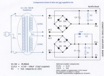
Hi Ray, voltage between V+ and V- should be 66Vdc. Voltage between PG and either V+ or V- should be 33Vdc.
Barry.
audio1st said:
Hi Ray, voltage between V+ and V- should be 66Vdc. Voltage between PG and either V+ or V- should be 33Vdc.
Barry.
Hahahah yes! I had that brainwave about ten minutes after I read Peter's post! Colour me dunce.
Anyway I got it working. Between switch on and the amp sending out signal there's about a 3 second delay, then an extreme-high frequency noise that ascends until undetectable. Big "thud" when switching off but that's to be expected I thing.
Big question is: Why is it so quiet? I cranked my Wakonda to maximum volume to get verrry quiet playback out of the Gainclone. I connected it to rubbish panasonic speakers, my old missions and to some tang bands I have lying around.
Measured .5v and 85mA +/-5mA across the posts while running the amp.
I would make yourself scarce!
I think that I should! There's no sign of the dancing Scotsman is there?

Hi Nick
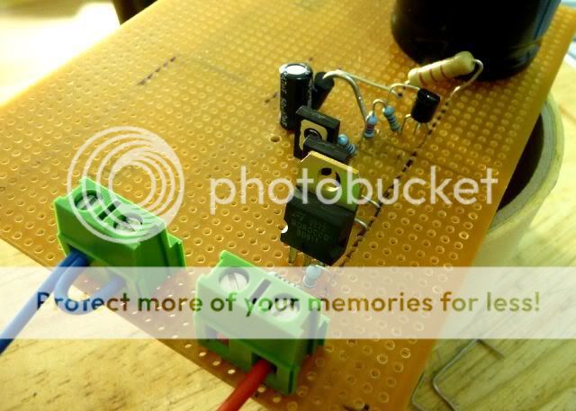
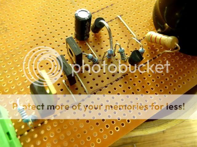
I have set out the +V components prior to soldering, can you see anything wrong?
I will cut the copper strips where necessary to avoid shorts. I am also going mount a heat sink for the BD911.
http://myweb.tiscali.co.uk/nuukspot/decdun/prp/supplies.htm
Thanks
Richard
P.S. Do you think Mr.T would mind helping this crazy fool?
Hfe/gain groups.
Hi Richard,
I'll try and help but am new to all this myself!")
According to page 2 of the data sheet... BD140 data ...you can get different 'gain groups' for the BD140's. Looks like the hfe or gain has been loosley matched by the manufacturer. I would imagine that your trannies without the '-16' suffix are just random and could therefore have any gain between the spec'd min & max.
I have no idea how this would effect Pedjas PSU... so you could either:-
a] Try matching them yourself if you have a suitable multimeter with this function (and also match the complementary BD139's).
b] Use transistor sockets and try different trannies - measure any differences,
c] Just stick 'em in any-old-how and see what happens.
d] Go here and see if anyone can advise.
HTH,
Steve
PS, no idea what 'R4' means either
Hi Richard,
I'll try and help but am new to all this myself!
According to page 2 of the data sheet... BD140 data ...you can get different 'gain groups' for the BD140's. Looks like the hfe or gain has been loosley matched by the manufacturer. I would imagine that your trannies without the '-16' suffix are just random and could therefore have any gain between the spec'd min & max.
I have no idea how this would effect Pedjas PSU... so you could either:-
a] Try matching them yourself if you have a suitable multimeter with this function (and also match the complementary BD139's).
b] Use transistor sockets and try different trannies - measure any differences,
c] Just stick 'em in any-old-how and see what happens.
d] Go here and see if anyone can advise.
HTH,
Steve
PS, no idea what 'R4' means either
Re: Hfe/gain groups.
Thanks for your input.
I hadn't thought of putting transistor sockets on the board. They are bugger to remove once soldered
Dr.X said:Hi Richard,
I'll try and help but am new to all this myself!
According to page 2 of the data sheet... BD140 data ...you can get different 'gain groups' for the BD140's. Looks like the hfe or gain has been loosley matched by the manufacturer. I would imagine that your trannies without the '-16' suffix are just random and could therefore have any gain between the spec'd min & max.
I have no idea how this would effect Pedjas PSU... so you could either:-
a] Try matching them yourself if you have a suitable multimeter with this function (and also match the complementary BD139's).
b] Use transistor sockets and try different trannies - measure any differences,
c] Just stick 'em in any-old-how and see what happens.
d] Go here and see if anyone can advise.
HTH,
Steve
PS, no idea what 'R4' means either
Nuuk said:I always try and measure and match transistors if at all possible. It usually removes a potential variable from the circuit!
Thanks for your input.
I hadn't thought of putting transistor sockets on the board. They are bugger to remove once soldered
The transistors in this reg PSU do not need to be matched.
Higher gain (hFE) will give slightly improved performance, but the improvement may not be audible and may be nearly immeasurable.
But you will need to measure the hFE at the operating currents that each transistor is set to in the regulator. Do not use an hFE check from a DMM.
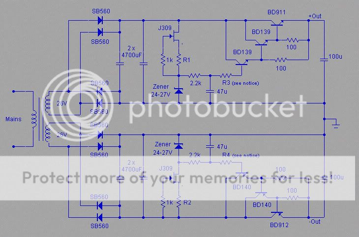
Can anyone explain why both emitter resistors are 100r when one transistor has ~600mV across the resistor and the other has ~1200mV across it?
Higher gain (hFE) will give slightly improved performance, but the improvement may not be audible and may be nearly immeasurable.
But you will need to measure the hFE at the operating currents that each transistor is set to in the regulator. Do not use an hFE check from a DMM.
Can anyone explain why both emitter resistors are 100r when one transistor has ~600mV across the resistor and the other has ~1200mV across it?
Can anyone explain why both emitter resistors are 100r when one transistor has ~600mV across the resistor and the other has ~1200mV across it?
Pedja quite rightly has had to draw a line on answering queries about his DIY projects. But he may be inclined to answer questions raised in that diyhi-fi.org thread.
AndrewT said:The transistors in this reg PSU do not need to be matched.
Higher gain (hFE) will give slightly improved performance, but the improvement may not be audible and may be nearly immeasurable.
But you will need to measure the hFE at the operating currents that each transistor is set to in the regulator. Do not use an hFE check from a DMM.
Can anyone explain why both emitter resistors are 100r when one transistor has ~600mV across the resistor and the other has ~1200mV across it?
Nuuk said:
Pedja quite rightly has had to draw a line on answering queries about his DIY projects. But he may be inclined to answer questions raised in that diyhi-fi.org thread.
Hi Andrew
Thanks for your reply, its very useful.
I will post a couple of questions on the other forum and report back.
Richard
AndrewT said:Can anyone explain why both emitter resistors are 100r when one transistor has ~600mV across the resistor and the other has ~1200mV across it?
He says...
The quiescent currents pulled by the resistors are about 12mA through the first, and 6mA through the second Darlington transistor. The second transistor will however conduct also the base current of the third transistor (which is equal to the current pulled by the amp divided by its hFE), whereas the increase of the base current of the second transistor, and thus the change in the current conducted by the first transistor will be practically negligible. That’s why I considered harmless to increase a bit the current through the first transistor. It is not really essential, and in fact I lately decreased it to about 5mA, using 220R.
Richard
- Home
- Amplifiers
- Chip Amps
- Chip amp power supply- a beginners guide