Nuuk said:OK, I'm reading off the same page now!")
The second one is the one that I am using, ie the 'final' version.
I am just putting together yet another order! What wattage resistors did you use?
Do you think you could post a pic of the power supply as it would be handy to cross refer
(Don't bother if its tucked away)
Most of the resistors are 0.25v and that one on the input side looks to be 0.6W.
From DD!!!!
From DD!!!!
An externally hosted image should be here but it was not working when we last tested it.
Nuuk said:Most of the resistors are 0.25v and that one on the input side looks to be 0.6W.
From DD!!!!
An externally hosted image should be here but it was not working when we last tested it.
Thanks Nick
I seem to miss items on your site for some reason. Id stack your web programmer
Did you use 'ST' transistors?
I seem to miss items on your site for some reason. Id stack your web programmer Did you use 'ST' transistors?
I haven't got room to stack myself anywhere!
I can't remember the make of the transistors but I think I got them from Cricklewood Electronics!
Nuuk said:
I haven't got room to stack myself anywhere!
I can't remember the make of the transistors but I think I got them from Cricklewood Electronics!
I spotted that typo!
I spotted that typo!
Yes but you should be paying more attention to your safety grounding or Uncle Andrew will be on your case!
Nuuk said:
Yes but you should be paying more attention to your safety grounding or Uncle Andrew will be on your case!
Don't I know it!
Tripmaster said:Are those carbon resistors attached to the pins of the slitfoils acting as a high frequency filter? What value are they?
No they are bleeder resistors. 2K2 2/W from memory.
AndrewT said:Hi Ray,
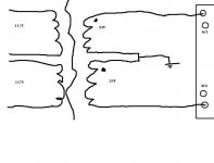
you've got a dual polarity supply from dual secondary transformer.
Middle connection is treated as zero volts.
The other two connections from the PSU are +33Vdc and -33Vdc.
All normal for this 24Vac transformer.
audio1st said:
Hi Ray,
It looks as if you have 2 white wires at V- and 2 red wires at V+..
I cant see where PG- and PG+ are connected, have you just tied them together?
They need to connect to the AMP board ground..
Please let us know how you have connected these wires.
Barry..
Sorry I'm so dumb, you guys are gents for helping me so much.
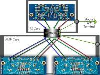
I've got two wires on V+ and V-, PG+ and PG- are wired to the ps chassis ground, which is in turn wired through the connector cable to the amp boards star ground and by way of that to the chassis ground for the amp enclosure. Here comes a diagram:
Attachments
AndrewT said:Hi Ray,
you've got a dual polarity supply from dual secondary transformer.
Middle connection is treated as zero volts.
The other two connections from the PSU are +33Vdc and -33Vdc.
All normal for this 24Vac transformer.
So Andrew...
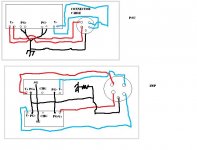
In order to treat the middle connection as zero I do this (see crude diagram), right?
Is only having one of two holes in AC1/AC2 going to work?? Doesn't that defeat the rectifier?
Attachments

sharing the PSU currents across two amplifiers has nothing to do with halving the PSU voltage.
The PSU has two halves each half has an output voltage ~ 1.5Tines the Vac of each transformer secondary Series connect the two output voltages at the rectifier PCB and you get +-Vdc ~= 1.5 times Vac + Vac.
You can use either a single rectifier to achieve this +-Vdc or you can use dual rectifiers to get similar +-Vdc.
The single rectifier version series connect trhe secondaries before the rectifier and can use a dual secondary transforme ror a centre tapped transformer.
The recent diagrams posted here show a dual rectifier version that must use a dual secondary transformer. The series connection of the supplies is after the rectifier in this case.
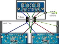
audio1st said:Hi Ray, the second picture is wrong.. The layout you have at the moment should work but may hum.
Below is my suggestion..
We may have to look at the Amp boards next?
Barry,
That's a beautiful diagram and I was using such setup successfully in AMP-1 for many years. That amp was dual mono with separate power feed to each channel.
When I tried to use similar approach in Patek or an Integrated Amp some people reported hum problems, so I modified ground wiring and that was better.
So if would be so kind, can you adjust the diagram in a way that OG points (on amp boards) are connected together and PG- and PG+ wires from power socket connect centrally to that connection, like in a picture here: http://audiosector.com/images/patek2/patek2_01.jpg
- Home
- Amplifiers
- Chip Amps
- Chip amp power supply- a beginners guide