! said:
All you need to do is get a standard light bulb socket, the type that screws to a wall or ceiling. You then wire it in series with one of the AC inputs to the transformers.
Previously I thought you meant the toroids themselves were humming because the windings were loose. Do you mean there is no noise coming directly from them, only noise on the output of your amp?
If the noise comes directly from them, the fix is kind of hackish, you would take the outer wrap off and re-wrap it, ideally smothering the windings in non-conductive epoxy to fix the coils in place first.
If the hum or hiss is on the output of the amp, you don't have a shielded circuit so try totally enclosing it in a grounded metal housing. Also ground loops can make it hum, I can't tell so much from the pictures but see if you have any ground loops and are using a star ground topology.
I also tweaked a T-Amp and agree, really nice crisp sound but output power is very limiting if the speakers are not very high efficiency or more volume is desired. From what I recall a switching PSU causes a little distortion but some say it's livelier, that they consider it better that way. On mine I used a basic LM317 linear regulator and decided that was right for me.
Is the noise only when it's turned on or off? I don't remember on your chipamp chip, but some have a mute circuit built in which can address on/off pop. Beyond that, it shouldn't be that the toroids are oversized for the application.
You did not mention your source, is it AC grounded? We don't know the exact amp circuit either unless I overlooked you posting it. Does it make noise equally when the source is plugged into it (but not playing audio) and when it is not?
AndrewT said:I have never built a Gainclone.
The circuit sucks.
I have only worked with the 3886 chip and it switches on and off silently and plays adequately.
It is easily beaten by any competent discrete amplifier.
I mean that the toroids themselves are humming when turned on! That is even if not connected to the PSU or AMP or sources, etc.
So you would suggest to almost dismantle it and try to rewind the wires again in some more "close" or "equidistant" way? Woha.. is this something doable?
")
So basically you guys really convinced me, I'll move to a 3886 based amp asap.. Andrew, do you thing the chipamp.com based lm3886 pcbs are acceptable? I'll anyway try to do my best doing star grounding, disconnection networks, snubbering, and changing some resustors value based on some tests, etc.
But still I'd need to find some decent and non noisy trafos for it: can you confirm that the trafos you guys use (for instance on the 3886 chips) "alone", are not noisy? i.e. you can not hear any annoying sound coming from your boxes/enclosures while no music is being played (so I do not intend from the speakers but really from your boxes, ok let's say at half a meter distance if it is perceivable)?
About the T-Amp: maybe I could improve them by using a toroid also there, but only if a non noisy one!
Thanks,
tent:wq
PS: I'm right now building the "lamp-tester"..
Before it gets lost
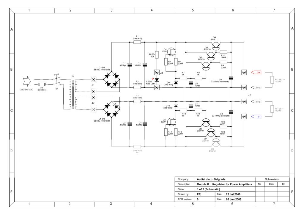
bmwpowere36m3 said:I'm interested in building a "regulated PSU" for my LM3886 gainclone project. I plan on building it for maximum output @ 4 ohms, just in case so I have a flexible system that'll work with a variety of speakers. So with a planned 25-30 Vcc, the continuous output would be ~68W (2x, stereo). After much reading I'd like to build Pedja's Discrete PSU (Module R), however on his site the listed schematic follows:
and on Nuuk's is:
An externally hosted image should be here but it was not working when we last tested it.
Differences (Pro's & Con's)? R1-R4 are different, in the top schematic he mentions they are charging resistors for the second set of capacitors. Also neither include bleed resistors on the capacitors.
Looking at commonly available zeners' (25, 27, 28, & 30 V), in the module R manual he lists Vishay BZX79 which seem no longer to be manuf. What should I looked for, 500mW power dissipation, DO-35 package, etc...
Also trafo secondary voltage, the manual mention selecting a voltage at least 4V higher than the zener's with 3-4 V on top of that fine for headroom. Is this voltage pre or post rectification? i.e. if I chose to use a 27V zener, then would a secondary voltage of 22 V work (post rectification 31 V)? Finally VA rating conservatively 250VA should be enough, or more or less?
AndrewT said:NO!!!!
check the output offset (mVdc) and the output noise (mVac) with various combination of input conditions and at start up and switch off. Do this with no load on the output.
Repeat with a dummy load (~8r0) and ensure you are not sending large offsets nor large voltage pulses to the speaker terminals before you add on the speaker load.
Use the bulb tester for every new combination or modification.
If the bulb stays off, this is where the switched version becomes handy. Just hold the bypass switch down to check the modification at full mains voltage.
Ok, I'll try it.
With "various combination of input conditions" do you mean with some CD playing on the inputs for example? With no sound, etc?
tent:wq
tent said:I mean that the toroids themselves are humming when turned on! That is even if not connected to the PSU or AMP or sources, etc.
So you would suggest to almost dismantle it and try to rewind the wires again in some more "close" or "equidistant" way? Woha.. is this something doable?
I was suggesting that the original problem may be that when it was made it was not wound tight enough, but it may be equally hard to wind it tight enough by hand so no, I am not suggesting you try to rewind it. Plus, the lacquer on the windings may have become brittle as it aged so it could crack off leaving uninsulated wires.
What I was suggesting is taking off the wrapping tape around the windings and putting new wrapping tape on very tightly, and/or setting the whole thing in epoxy.
However, for the amount of time this would take and because the amp doesn't need those big, 2 x 200VA transformers, I feel the best suggestion is to just find an inexpensive center tapped replacement transformer.
But still I'd need to find some decent and non noisy trafos for it: can you confirm that the trafos you guys use (for instance on the 3886 chips) "alone", are not noisy? i.e. you can not hear any annoying sound coming from your boxes/enclosures while no music is being played (so I do not intend from the speakers but really from your boxes, ok let's say at half a meter distance if it is perceivable)?
About the T-Amp: maybe I could improve them by using a toroid also there, but only if a non noisy one!
Thanks,
tent:wq
PS: I'm right now building the "lamp-tester".. [/B]
Any transformer is designed for a certain frequency range and load, if it makes noise within that range it should be considered poor or defective. Sometimes the noise is slight enough people ignore it, but you don't have to settle for having it.
When the transformer is in a different enclosure than the amp, there is no need to use a toroid type, they let more electrical noise get to the amp than a more common laminated E-core type. The main reason people use a toroid transformer is when it is in the same casing as the amp because it has a smaller more directional magnetic field.
A T-Amp rejects lower frequency noise quite well, it isn't as important to use any particular type of PSU with it, what helps it the most is to have a 220uF or larger low ESR capacitor on the amp PCB to replace the original electrolytic capacitor, and of course then the other various tweaks proposed all along on the internet for T-amps.
About the lamp tester, previously I mentioned using a light bulb socket type with a base that screws to the wall or ceiling. What I meant was, this allows it to be screwed to a sheet of wood. The logical arrangement of the circuit is to wire it in series with the AC input to the transformer, but for the most versatile testing setup you would add a few more parts.
The best arrangement is to mount the bulb socket, a DPST switch, and an AC outlet to a wood sheet. Then tack down an AC input cord with a plug going to the AC wall outlet. The result is you have wall outlet to switch to bulb to AC outlet in series on one AC lead, and AC outlet to switch to the other AC outlet terminal on the other wire lead.
By building it like that, you can plug anything with a power cord into it without rewiring either the bulb test rig or the (amp) powered equipment.
bmwpowere36m3 said:Before it gets lost
I have previously built a zener/pass-transistor regulated PSU which wasn't exactly like either of those, but was somewhat similar. The amp sounded good with it, but ultimately I feel it would be just as well to use an IC, a linear regulator plus pass transistor instead of a zener for regulation, an example of the basic circuit I mean can be found in National Semiconductor's LM317 datasheet.
R1-R4 form an RC filter but most people don't seem to feel it is worthwhile since they omit resistors in these positions (regardless of whether the rest of the PSU is the same, anyone could use a circuit topology with the equivalent of R1-R4 and 4 instead of 2 capacitors.
You could include bleed resistors on the capacitors, it is not a bad idea at all. It's just that with any basic circuit topology lots of things can be added for different reasons, some very good reasons and some just tweaks with less and less improvement the more parts are added on, generally speaking (though there are of course exceptions).
To determine zener power rating you will have to calculate how much power is dissipated, which depends on the resistor values between the power rail and the zener, how much current is passed * voltage difference between the zeners and the pre-pass-transistor voltage. If the right resistor values are used, yes you should be able to use a 500mW zener, with the pair of BD139s (Or BD140 on the other rail) you have enough gain that the current shouldn't need be very high at the zener. The package type you use depends on convenience in mounting to the circuit board you want to use, or since it's a DIY design you can pick a zener with easy availability and design the circuit board around using that type.
The input voltage requirement would be the voltage after the rectification. 31V post rectification is cutting it too close with a 27V zener, unless you are measuring the 31V with the transformer at full load, full output power. The point of the additional 3-4V margin is that under load the initial voltage before the pass transistors (BD911/912) will have dropped some so that 3-4V is a margin to allow for voltage drop.
So based on what you have mentioned of the recommendations, if you want to use a 27V zener you would want at least 34V after the rectification stage, or
(34 + 1.0 [approx voltage drop of two schottky diodes SB560]) / 1.41 = 25V AC rating on transformer.
Edit: What I wrote above is not quite right, since a transformer is rated for it's voltage at the rated output current. If it's rated output current is similar to what you expect the amp to use, the 3-4V margin can be reduced to almost zero, if it's rated output current is higher than you'd use, the margin might even become a negative number. If it's rated output current is lower than amp peak current consumption the number might (but is unlikely to unless the transformer has very poor regulation or is much too small for proper use) be higher than 3-4V.
Either way, that is only the additional margin, no matter what the additional margin is you still need 4V more between rectification and pass transistor than the voltage of the zener(s).
Personally what I like to do is pick the transformer I want, then based on it's voltage rating and post-rectification stage voltage, then pick the zener value so that you don't have so much loss (don't need as big a heatsink) on the pass transistor, though this also requires a transformer with a voltage rating not too high, so you can do this without exceeding the max voltage you amp can tolerate.
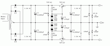
If you wanted some other voltage and can't find the right zener value for it, you can just put two zeners in series. For example 33V zener then 2.4V zener = 35.4V zener. Attached is a more simplified pass transistor type PSU showning two in series, though it uses smaller resistor values because that causes higher base current to drive a single darlington transistor instead of getting gain in drive current from two BD139 before the BD911.
Attachments
bmwpowere36m3 said:Before it gets lost
Something else about building a zener / pass-transistor type PSU, you may want to buy several zeners and pick the ones that measure to be the closest match in voltage, so your V+ to Gnd, and Gnd to V- voltages are as close to the same value as possible.
It seems that the higher the zener voltage rating is, the more variation there is in actual voltage of each zener... something about rating them for % accuracy, means the higher the voltage rating the more that % * voltage can result in deviation from spec'd voltage.
! said:
I have previously built a zener/pass-transistor regulated PSU which wasn't exactly like either of those, but was somewhat similar. The amp sounded good with it, but ultimately I feel it would be just as well to use an IC, a linear regulator plus pass transistor instead of a zener for regulation, an example of the basic circuit I mean can be found in National Semiconductor's LM317 datasheet.
R1-R4 form an RC filter but most people don't seem to feel it is worthwhile since they omit resistors in these positions (regardless of whether the rest of the PSU is the same, anyone could use a circuit topology with the equivalent of R1-R4 and 4 instead of 2 capacitors.
You could include bleed resistors on the capacitors, it is not a bad idea at all. It's just that with any basic circuit topology lots of things can be added for different reasons, some very good reasons and some just tweaks with less and less improvement the more parts are added on, generally speaking (though there are of course exceptions).
To determine zener power rating you will have to calculate how much power is dissipated, which depends on the resistor values between the power rail and the zener, how much current is passed * voltage difference between the zeners and the pre-pass-transistor voltage. If the right resistor values are used, yes you should be able to use a 500mW zener, with the pair of BD139s (Or BD140 on the other rail) you have enough gain that the current shouldn't need be very high at the zener. The package type you use depends on convenience in mounting to the circuit board you want to use, or since it's a DIY design you can pick a zener with easy availability and design the circuit board around using that type.
The input voltage requirement would be the voltage after the rectification. 31V post rectification is cutting it too close with a 27V zener, unless you are measuring the 31V with the transformer at full load, full output power. The point of the additional 3-4V margin is that under load the initial voltage before the pass transistors (BD911/912) will have dropped some so that 3-4V is a margin to allow for voltage drop.
So based on what you have mentioned of the recommendations, if you want to use a 27V zener you would want at least 34V after the rectification stage, or
(34 + 1.0 [approx voltage drop of two schottky diodes SB560]) / 1.41 = 25V AC rating on transformer.
Edit: What I wrote above is not quite right, since a transformer is rated for it's voltage at the rated output current. If it's rated output current is similar to what you expect the amp to use, the 3-4V margin can be reduced to almost zero, if it's rated output current is higher than you'd use, the margin might even become a negative number. If it's rated output current is lower than amp peak current consumption the number might (but is unlikely to unless the transformer has very poor regulation or is much too small for proper use) be higher than 3-4V.
Either way, that is only the additional margin, no matter what the additional margin is you still need 4V more between rectification and pass transistor than the voltage of the zener(s).
Personally what I like to do is pick the transformer I want, then based on it's voltage rating and post-rectification stage voltage, then pick the zener value so that you don't have so much loss (don't need as big a heatsink) on the pass transistor, though this also requires a transformer with a voltage rating not too high, so you can do this without exceeding the max voltage you amp can tolerate.
If you wanted some other voltage and can't find the right zener value for it, you can just put two zeners in series. For example 33V zener then 2.4V zener = 35.4V zener. Attached is a more simplified pass transistor type PSU showning two in series, though it uses smaller resistor values because that causes higher base current to drive a single darlington transistor instead of getting gain in drive current from two BD139 before the BD911.
Great, well I'm planning around the amp's continuous power rating of 68W at 4 ohms with a 28Vcc. Based on the spec sheet that equates to an Iopeak of 5.8A and looking at trafos of 250VA size their rating is (25-30 V secondary) is 4-5 A. So for the "most" part, when not taxing the system, the current demands of the amp will be less or equal to the trafo. So the 3-4V headroom is sufficient, correct?
bmwpowere36m3 said:
Great, well I'm planning around the amp's continuous power rating of 68W at 4 ohms with a 28Vcc. Based on the spec sheet that equates to an Iopeak of 5.8A and looking at trafos of 250VA size their rating is (25-30 V secondary) is 4-5 A. So for the "most" part, when not taxing the system, the current demands of the amp will be less or equal to the trafo. So the 3-4V headroom is sufficient, correct?
Yes, to result in 28Vcc a 4-5A transformer rated for 25VAC would be good.
shorted and open circuit input.tent said:"various combination of input conditions" do you mean with some CD playing on the inputs for example? With no sound, etc?
low volume and medium volume and high volume settings.
That's 6 combinations to try.
repeat all 6 at turn off and again at turn on.
We're up to 18 tests so far, before you add any load to the output.
two channels of 68W+68W require a transformer between 136VA and 272VA.bmwpowere36m3 said:the amp's continuous power rating of 68W at 4 ohms with a 28Vcc. Based on the spec sheet that equates to an Iopeak of 5.8A and looking at trafos of 250VA
Your 250VA is perfect.
The 5.8Apk only applies to sinewave into a resistive (non reactive) load.
The transient peak current into a 4ohm reactive speaker load could be around three times this, i.e. ~17Apk.
That is way in excess of the chipamp specification. The transformer can easily meet this transient requirement.
Hi again,
ok all is clear.
Only the exact meaning of:
For the rest I'll do the measurements and see what is the result, also the bulb test result with different rated bulbs.
Now basically I think that next w/e I'll go to take a new toroid with dual secondaries and see if I'll get a good one this time!
Thanks,
tent:wq
ok all is clear.
Only the exact meaning of:
is a bit unclear to me.AndrewT said:shorted and open circuit input.
For the rest I'll do the measurements and see what is the result, also the bulb test result with different rated bulbs.
Now basically I think that next w/e I'll go to take a new toroid with dual secondaries and see if I'll get a good one this time!
Thanks,
tent:wq
! said:Darn, Cal says I have to change my username due to the forum software changes. It'll be....
like a disguise !
well after continued email, Cal is, I feel, unreasonable, so good luck, adios, etc, I'm outta here. Too much BS for what was supposed to be an enjoyable hobby.
AndrewT said:open circuit input = the input RCA socket with no interconnect inserted.
shorted input = insert a shorting RCA plug into the input RCA socket.
A shorting plug can be assembled from an RCA plug with the ground tag/barrel soldered to the input/line tag.
Ok I did all those measurements (and I had to repeat them also for both channels right?!?
) and basically in all situations I can read c.a. 104-107mV DC, no difference if shorted input or not (and I have no volume POT, the volume is anyway ridiculously low): sounds bad, right? Something is probably wrong in the schematic or in my work?And even worse: the only situation where I can read a different measurement is at power off where I get a spike reaching 1400-1600mV DC, could this be harmfull to the speakers? (I did already test with speakers BTW.. I hear a loud POP at turning the amp off)
While, when turning on, no POPs nor spikes, just quick and smooth rise to the ugly 107mV DC
Any suggestions?
! said:
well after continued email, Cal is, I feel, unreasonable, so good luck, adios, etc, I'm outta here. Too much BS for what was supposed to be an enjoyable hobby.
!: so only because of a nickname change?
Well "escalmationpoint" would be a nice and short nick too, isn't it?
Besides jokes I'd try to see if the databse of the new forum would be directly importable from the old thus maintaining old nicks, or in case if this is impossible, maybe "e!" would also be an interesting idea..
cheers,
tent:wq
I had another look at post371.
The 13Vac transformer outputs a lot of current.
To achieve this current ability they have used a bi-fillar winding rather than a thicker single winding.
You could open up the insulation and separate the two windings to create a 13V+13V transformer. Bring all four wires to the output leads.
Fit flexible output leads at the same time and make them too long initially. You can cut them short later.
What is the mains input voltage when you measure the unloaded secondary output voltage?
AndrewT said:I had another look at post371.
The 13Vac transformer outputs a lot of current.
To achieve this current ability they have used a bi-fillar winding rather than a thicker single winding.
You could open up the insulation and separate the two windings to create a 13V+13V transformer. Bring all four wires to the output leads.
Fit flexible output leads at the same time and make them too long initially. You can cut them short later.
What is the mains input voltage when you measure the unloaded secondary output voltage?
Hi Andrew,
yes you're right the two wires of the secondary coming out of both transformers are in reality made of two wires connected togheter.. (see also a foto of the trafo earlier)
But not so sure what you propose about bringing "all four wires to the output leads", "same time", "too long", etc.
Did you mean connect them (separated and prolonged) to AC1, AC1_, AC2 and AC2_?
But if I separate the two wires from the trafo don't it just be 6 volts or similar? (i.e. 6v-0v 0v-6v)
I'll try it out anyway, would this probably silent the trafo also?
The mains input voltage is at unloaded status: 236V AC
Thanks,
tent:wq
(PS: my english is probably a bit limited.. sorry..)
Hi,
a bi-fillar winding has two separate (insulated) wires wound on the core.
If you separate the wires into two windings, each produces the same voltage but has half the current capacity.
A 10A, 13.5Vac bi-fillar secondary becomes 5A, 13.5Vac + 5A, 13.5Vac when separated.
This will not solve the noise problem. It will allow you to run the good transformer with the voltage you need.
When you have altered the bad transformer, you may discover that it has been wound/wired incorrectly and now operates quietly, but this is unlikely.
When you feed 236Vac into the transformer, what is the secondary Vac when there is no load on the secondary?
AndrewT said:Hi,
a bi-fillar winding has two separate (insulated) wires wound on the core.
If you separate the wires into two windings, each produces the same voltage but has half the current capacity.
A 10A, 13.5Vac bi-fillar secondary becomes 5A, 13.5Vac + 5A, 13.5Vac when separated.
This will not solve the noise problem. It will allow you to run the good transformer with the voltage you need.
When you have altered the bad transformer, you may discover that it has been wound/wired incorrectly and now operates quietly, but this is unlikely.
When you feed 236Vac into the transformer, what is the secondary Vac when there is no load on the secondary?
Wow, I see, So I'll try to disassemble the trafo and see what happens now..
The secondary output load is 13.4Vac.
Now I tried also with the light bulb tester and curiousely enough the 60W bulb stays on at amp powered on!! not really bright but also not dim..
I'm going to recheck everything again now.. grr..tent:wq
- Home
- Amplifiers
- Chip Amps
- Chip amp power supply- a beginners guide