The PSU is built perfectly. Wiring perfect. Still shorting when PGND's are connected. The trafo I am using has x2 CT leads that were soldered togeth. I seperated them and used each seperately...one for AC1 the other for AC2. My previous trafo only had a single wire for the CT that I had to splice x2 wires to in order to input to both AC1 and AC2 on the PSU. Maybe I shouldn't have seperated the CT wires?
Jeff
Jeff
something not perfect!jmillerdoc said:The PSU is built perfectly. Wiring perfect. Still shorting when PGND's are connected.
jmillerdoc said:I seperated them and used each seperately...one for AC1 the other for AC2.
Jeff
Hi Jeff,
Have you used the correct separated CT wire with it's associated AC1 and AC2 winding?
still seems to be shorting
I have tried swapping the CT leads and it didn't make a difference...so 1 out of 2 tries I guess I did connect the proper lead...still the trafo makes a high frequency zapping noise as soon as I connect the PGND's. I am going to pull the other PSU out of the amp and try to do it with this one although I believe the PSU is perfectly fine, It worked fine before when connected to one of the LM3886 boards.
I guess I should move on to my second question..where exactly does the PGND's connect on the LM3886 board. I am building a point to point and figured if maybe I tried to connect the PGND's at the LM3886 that may work. I just wouldn't know the respective points on the LM3886 P2P that correspond to Brian's design.
Thanks,
Jeff
trafo with single secondary windings
Hi people,
really interesting forum.. was lurking a lot till I finally decided to buy some kits from brianGT and get to the real work: my first chipamps.
I'm starting with the LM 1875 kit now and am stuck in cabling the toroid to the PSU:
I have TWO toroidal transformers having ONE single primary (220V) and just ONE single secondary output windings (at 13.5V).
Will I be able to use those trafos? My real question is how do I connect those trafos to the AC1, AC1_, AC2 and AC2_ posts on the PSU PCB?
I suppose I need two PSU PCBs since the ones I have have only one rectifying bridge (4 MURs) per PCB, right? no way to connect two trrafos on the same bridge (since i have 4 ACx holes") ?
?
Ok sorry for the really silly questions but was not able to spot on the forum anyone using single secondary toroids on this forum (afaik), maybe a bad idea in general?
Thanks in advance for any hint!
tent:wq
Hi people,
really interesting forum.. was lurking a lot till I finally decided to buy some kits from brianGT and get to the real work: my first chipamps.
I'm starting with the LM 1875 kit now and am stuck in cabling the toroid to the PSU:
I have TWO toroidal transformers having ONE single primary (220V) and just ONE single secondary output windings (at 13.5V).
Will I be able to use those trafos? My real question is how do I connect those trafos to the AC1, AC1_, AC2 and AC2_ posts on the PSU PCB?
I suppose I need two PSU PCBs since the ones I have have only one rectifying bridge (4 MURs) per PCB, right? no way to connect two trrafos on the same bridge (since i have 4 ACx holes
?Ok sorry for the really silly questions but was not able to spot on the forum anyone using single secondary toroids on this forum (afaik), maybe a bad idea in general?
Thanks in advance for any hint!
tent:wq
Re: trafo with single secondary windings
Assuming both transformers are identical (you would not want to use two dissimilar ones even if they seem rated the same as ratings can vary with other parameters) you would take one secondary and connect it to the opposite end of the other secondary, thus creating the equivalent of a single center tapped transformer, the two connected together being the center tap.
When you do that, do the opposite for the high-side input windings meaning the mains AC power hot goes to the same end of the winding on each transformer, mains AC neutral goes to the other end.
Then you just wire it to the single bridge as anyone else using a single bridge, the output of which becomes V+ and V- rails while the center tap is ground.
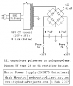
I mean like in the folllowing picture, but I don't recall the pad designations for the circuit on the PCB you have.
That's a fairly elaborate setup for a little LM1875, are you sure you want to devote the parts, PCB and larger chassis to such a low power class A/B 1 channel amp chip? I suppose though with the low voltage transformers the opposite could be said about building with a chip like LM3886, then it would be good to switch transformer instead of chip, it just seems a lot of work for a single 20W channel.
It's not that I'm putting it down as bad per se, I've built something even lower power per channel with LM4752 and it sounds good for what I needed it for, but I wouldn't go to much time or expense for one. On my LM4752 amp I just reused an old 1.something amp AC/DC wall wart that I upgraded the capacitor in, and put the amp in a tiny plastic enclosure barely big enough for output, input, and a socket 7 sized CPU heatsink sticking out the back.
tent said:Hi people,
really interesting forum.. was lurking a lot till I finally decided to buy some kits from brianGT and get to the real work: my first chipamps.
I'm starting with the LM 1875 kit now and am stuck in cabling the toroid to the PSU:
I have TWO toroidal transformers having ONE single primary (220V) and just ONE single secondary output windings (at 13.5V).
Will I be able to use those trafos? My real question is how do I connect those trafos to the AC1, AC1_, AC2 and AC2_ posts on the PSU PCB?
I suppose I need two PSU PCBs since the ones I have have only one rectifying bridge (4 MURs) per PCB, right? no way to connect two trrafos on the same bridge (since i have 4 ACx holes
Ok sorry for the really silly questions but was not able to spot on the forum anyone using single secondary toroids on this forum (afaik), maybe a bad idea in general?
Thanks in advance for any hint!
tent:wq
Assuming both transformers are identical (you would not want to use two dissimilar ones even if they seem rated the same as ratings can vary with other parameters) you would take one secondary and connect it to the opposite end of the other secondary, thus creating the equivalent of a single center tapped transformer, the two connected together being the center tap.
When you do that, do the opposite for the high-side input windings meaning the mains AC power hot goes to the same end of the winding on each transformer, mains AC neutral goes to the other end.
Then you just wire it to the single bridge as anyone else using a single bridge, the output of which becomes V+ and V- rails while the center tap is ground.
I mean like in the folllowing picture, but I don't recall the pad designations for the circuit on the PCB you have.
That's a fairly elaborate setup for a little LM1875, are you sure you want to devote the parts, PCB and larger chassis to such a low power class A/B 1 channel amp chip? I suppose though with the low voltage transformers the opposite could be said about building with a chip like LM3886, then it would be good to switch transformer instead of chip, it just seems a lot of work for a single 20W channel.
It's not that I'm putting it down as bad per se, I've built something even lower power per channel with LM4752 and it sounds good for what I needed it for, but I wouldn't go to much time or expense for one. On my LM4752 amp I just reused an old 1.something amp AC/DC wall wart that I upgraded the capacitor in, and put the amp in a tiny plastic enclosure barely big enough for output, input, and a socket 7 sized CPU heatsink sticking out the back.
Attachments
Hi !,
well yes you are probably right, but if I understood it right this LM1875 should have sonically the same quality of the LM3875/LM3886 ones but just with less output power, since is going to be used in a small room but where I anyway would like to have very good results and first of all very low hum/hiss (it will reproduce mainly a piano sound). Or is this 20W anyway compromising this expectations I have and the power is not enough di per se to let for example a piano sound fill in well the room without clipping etc?
Consider that I'm also thinging if putting it in two separate housings if necessary.
And consider also that this is my first attempt with LM based gainclones, previousely I had only experience with T-AMPs, so this is my first work here, let's say, and I would start now with a LM1875 and later I would like to build a LM3886 or LM4780 for my main system to put on the living room but doing it with the experience of this first attempt.
Last consideration: I already have two identical toroids doing 13.5V, no other way to use them for other LM's, right? My only concern was since they only have one secondary winding coming out if they would fit.
Ok, so coming back to my original question, I'm using "chipamp.com's" based PCB you can also see here: http://www.chipamp.com/images/lm1875-5.jpg
And you would say to connect my two trafos this way?
Mains: Trafos: Output to bridge:
220V L 13V
o--------+--+------------o AC1
|t1|
|--------+--+----| 0V ? o AC1_
|--------+--+----|-------o AC2
|t2|
o--------+--+------------o AC2_
220V N 13V
Am I correct? So basically I have two wire coming from each trafo on the primary 220V and I connect two of those (one from each different trafo) toghether and the two remaining one from each trafo to mains. And the same with the two wires coming from each trafo on the secondaries at 13V: two, one from each trafo tied togheter and to 0V ground (AC1_ and AC2) and the remaining two, one from each trafo, one to AC1 and one to AC2_, right?
Thanks a lot,
tent:wq
PS: sorry for the poor ascii art drawing =)
Hi,
well I already tried this the first time before asking here and putting the primaries in parallel, and connecting the secondaries to the PSU single bridge, but then something went wrong and it seems not ok (the fuse on the main did blow "slowly" and thus luckily saving the rest.. so probably something is wrong on how I connect the secondaries... I did as said also here: two wires of the secondaries of the first trafo went on AC1 and AC1_, the other two wires of the second trafo went to AC2 and AC2_ but it seemd not ok.. what's wront?
tent:wq
PS: I also of course measured the secondaries of both toroids before connecting them on the PSU and on both Imeasured 13.5V difference with my tester set on ACV200...
audio1st said:Connect one transformer (secondaries) to ac1 the other transformer to ac2.
Connect the primaries in parallel.
I did this but the result was a blown 2A 220V fuse.. if you look at the schematics on the chipam.com for this LM1785 you'll notice that AC1_ and AC2 are connected togheter and that it is a single rectifying brideg.. I don't know if this is maybe the trouble/difference with other PSUs like the one of CarlosFM.. Maybe I should rather build one like Carlo's one with two bridges?
tent:wq
tent said:Hi,
well I already tried this the first time before asking here and putting the primaries in parallel, and connecting the secondaries to the PSU single bridge, but then something went wrong and it seems not ok (the fuse on the main did blow "slowly" and thus luckily saving the rest.. so probably something is wrong on how I connect the secondaries... I did as said also here: two wires of the secondaries of the first trafo went on AC1 and AC1_, the other two wires of the second trafo went to AC2 and AC2_ but it seemd not ok.. what's wront?
tent:wq
PS: I also of course measured the secondaries of both toroids before connecting them on the PSU and on both Imeasured 13.5V difference with my tester set on ACV200...
Are you sure you have the right orientation of each transformers' primarys, and of their secondaries? You might have wired them opposite each other so they are out of phase?
Leave the transformers disconnected from the PCB for the time being. Connect one end of the secondary from one transformer to the opposite end of the other transformer.
Connect the same ends of each transformer's primarys together so the transformer primaries are in parallel, then wire them to mains AC.
When power is turned on, measure the voltage between the non-joined ends of the secondary windings and compare to the voltage between either non-joined end and the joined portion in the middle. Voltage between the non-joined ends should be double the voltage between either end and the joined center tap.
If you join the wrong end of the secondary together the voltage of one will cancel out the other. The same will happen if you join the wrong end of the primary to the other transformer's primary.
Once you are sure the transformers are wired correctly, and to save fuses, I would temporarily place a several watt rated, a few dozen ohms power resistor in series with either transformer's secondary connection to the PCB. That way, you have current limiting so you aren't stressing any parts but you will be able to get an output voltage reading from the power supply PCB to see if it is correct. Do this without the amp connected to the power supply PCB, test each thing as simply as possible to make sure each works before wiring it to the amp.
Unless I overlooked it, you did not mention the current rating of the transformers or their type. It is possible too large an inrush current happens when the PSU is turned on because the fuse is undersized for the transformers and capacitance of the PSU. Even if you don't expect the amp to consume as much as 2A at full power, momentary inrush current may be higher than this.
Instead of just using a larger fuse which subjects the parts to more possible damage if something else is wrong still, you could temporarily place a low, under 10ohm power resistor in series on one of the primary windings to limit inrush current, then remove it once you are sure everything is working ok. If you have no power resistors you could temporarily remove the capacitors from the PSU PCB and measure the output voltage to be sure it is roughly what is expected to confirm the rest of the PCB is wired correctly without as large an inrush current.
If and when everything else seems to be working properly based on voltage measurements, if you are then still blowing fuses you may need to use a larger fuse or more safe would be to permanently place a NTC thermistor in series with the hot AC input, but it would need be one of low ohmic value because at the low continuous current levels the amp would use, the higher the value the more significantly it will drop the transformer output voltage.
Warning: when I wrote "connect" one end to the other, I didn't mean electrically connect, I meant connect your multimeter for a voltage reading.
Do not do what my prior post implied, and I apologize for the ambiguous wording I used. I always mean, take measurements with a multimeter to confirm each subcircuit is doing what you expect it to.
Do not do what my prior post implied, and I apologize for the ambiguous wording I used. I always mean, take measurements with a multimeter to confirm each subcircuit is doing what you expect it to.
Hi !,
ok this makes sense! I probably connected those two trafos out of phase! so simple and so stupid.. I'll try it out again just now (but still a bit scared about the warning of your second post.. should I consider the post edited an read it as I did?).
In any case my two toroids are 200VA each, so pretty powerfull ones for the two small LMs. And do you confirm that having two bridges would not be the case, as also it would not be possible with my trafos to connect only one trafo to the bridge?
I'm also wondering a lot why the chipamp kit did suggest to use a couple of 1500mF caps instead of two 10000mF, any idea, which are better with this particular LM chips I'm using?
Thanks a lot, I'll go further with my build today and let you know (I'll put also some photos if possible),
tent:wq
ok this makes sense! I probably connected those two trafos out of phase! so simple and so stupid..
I'll try it out again just now (but still a bit scared about the warning of your second post.. should I consider the post edited an read it as I did?).In any case my two toroids are 200VA each, so pretty powerfull ones for the two small LMs. And do you confirm that having two bridges would not be the case, as also it would not be possible with my trafos to connect only one trafo to the bridge?
I'm also wondering a lot why the chipamp kit did suggest to use a couple of 1500mF caps instead of two 10000mF, any idea, which are better with this particular LM chips I'm using?
Thanks a lot, I'll go further with my build today and let you know (I'll put also some photos if possible
),tent:wq
Hi all again,
ok I did the test again settupping it like ! suggested and it is working now (no fuse blew) at least with no bridge connected, only with the two trafos. And I read 13.4V difference between the connected point of the secondaries and the non connected ones; while I read 27V c.a. between the two non connected ones.
But hey I have a problem now! this means I do not have any more the 13.5V I needed for the LM1875 at 4ohm speaker load I was planning: now I have 27V (all before rectifying so they are going to rise by 1.4 c.a.) so this is probably something to go on an LM3886 at 8ohm speaker load! Do you confirm?
So what could I do next? Probably aske to do some other two trafos?
tent:wq
ehm.. and sorry for the bull**** I just told a couple of posts ago about having the double of V for my LM1875.. of course I should just consider the difference between gnd and + or - V so I still have 13.5 before rectifying.. So basically I need to buy other fuses and if you thing the caps are underextimated to take a couple of 10000mF tanks..
tent:wq
of course I should just consider the difference between gnd and + or - V so I still have 13.5 before rectifying.. So basically I need to buy other fuses and if you thing the caps are underextimated to take a couple of 10000mF tanks..tent:wq
Hi again,
ok current status is: I checked with 3.15A fuses and they did also blow and now with 4A fuses I have a stable setup even by turning on and off several times, so this seems the best for my two 200VA 2x13.5V toroids, and now I can read after the bridge a 18.7V between V+/- and GND.
Next step will be connecting amp and then speakers.. after I connect amp and check how many milliamps there are on the output for the speakers, can I do it simple as is with my multi or is it better to put some load between them like a 10ohm 5W resistor?
So now the missing questions for me are:
- Is it possible to use two bridges with my setup? (is it non sense? just parallel the out on two bridges, etc.)
- Is it possible to use just one of my two 13.5V toroids (with single secondaries) and the one bridge? (connectng only AC1 and AC2_, nothing on the 0V?)
- Would it be wiser/sinically better to change the 1500uF caps with some 10000uF or any other value? I also put under the current 1500 caps a 2200 resistor at 2W.
- Is it wise/sonically better to snubber the bridge? If so would you suggest me on this PSU+trafos something like a 2.2nF between the secondaries coming out the toroid?
Thanks in advance,
tent:wq
- Home
- Amplifiers
- Chip Amps
- Chip amp power supply- a beginners guide