OK, I always stop here to read.( the more we read... the more we learn)I would like to hear from you. Let us read the comments about your power supply capacitance and it's components!.(LM3875/LM3886) most people use "small" caps on the power supply 4.7uf/10uf and 1,000uf next to the IC.
I started using 4.7uf,10uf on the power supply then 1,200uf and right now I am using 10,000uf per rail and 1,000uf Black gates next to the IC, I am using LM3875.
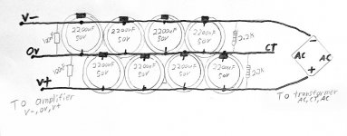
I am also using .01uf 400v 5% radial caps on each diode to eliminate some impurity...(These 0.01uF, "103") caps subtract rectifier noise, which reduces heat and radio interference)
All this started no to long ago with some caps testing (with alligator clips) it is easy and fast.at the end I liked the sound better with 10,000uf per rail, the bass is a lot tighter and deeper than using 4.7uf/10uf. I also try with 20,000uf per rail ,but I did not notice a change.
Now let us hear from you!
What IC (LM3875/LM3886)are you using?
Do you use "103" (.01uf) caps on your Bridge rectifier?
How much 'Capacitance" are you using per rail?
")
I started using 4.7uf,10uf on the power supply then 1,200uf and right now I am using 10,000uf per rail and 1,000uf Black gates next to the IC, I am using LM3875.
I am also using .01uf 400v 5% radial caps on each diode to eliminate some impurity...(These 0.01uF, "103") caps subtract rectifier noise, which reduces heat and radio interference)
All this started no to long ago with some caps testing (with alligator clips) it is easy and fast.at the end I liked the sound better with 10,000uf per rail, the bass is a lot tighter and deeper than using 4.7uf/10uf. I also try with 20,000uf per rail ,but I did not notice a change.
Now let us hear from you!
What IC (LM3875/LM3886)are you using?
Do you use "103" (.01uf) caps on your Bridge rectifier?
How much 'Capacitance" are you using per rail?
Mine uses 3x4700uF Nichicon per rail at the power supply, some cheap 100nF parallel with the diodes, 330uF near the chip (LM3886T). Loudspeakers are TQWT equipped with P.Audio PA-800K (8 inch woofer, 92dBm) and DT-300 (silk dome, 1 inch, 93dBm). I am quite happy with these, plenty of power, accurate and down low enough to move the furniture around.
Very nice ratza!
With 14,000uf per rail and 92db spl speakers.. it is enough to move those windows for sure!
I like silk tweeters too,they sound smoother than metal tweeter.metal tweeters tent to be too bright for my test.
I build my speakers ,I used 3rd order high pass acoustic slope and a 2nd order low pass acoustic slope to allow for the delay time between drivers this technique allows to both drivers to be acoustically in-phase with one another at the crossover frequency. I crossed it at 3,200 Hz. . I also installed zobel network (to keep impedance flat and steady) from 250 hz to 10 khz, the impedance is 8 ohms +/-0.5 ohm.
Mine are also made by myself. The total cost (including finishing) was around $300...$350. Passive crossover, 12dB/octave, crossing point at 1.8kHz. I am very satified with the sound, nice soundstage, not tiresome, so they'll stay around for a while.
Anyway, I forgot to mention that I have 100n decoupling caps on the power supply and on the IC board.
Anyway, I forgot to mention that I have 100n decoupling caps on the power supply and on the IC board.
+-30mF @ rectifier,
+-1mF near chip pins
+-100nF or 47nF on chip pins.
BTW,
a wideband chipamp driving medium to low sensitivity speakers cannot work properly with the main smoothing capacitance omitted.
Narrow band chipamp dedicated to treble or mid driving high sensitivity speakers require much less smoothing capacitance. You may find that moving the main smoothing from the rectifier to the chipamp works for this very specialised drive requirement.
AndrewT said:+-30mF @ rectifier,
+-1mF near chip pins
+-100nF or 47nF on chip pins.
. . .
Oooh. You're good! Dropping an anvil-size hint, are we?
Assuming that I had added 6600uf per rail at the power supply board and 470uF per rail at the amplifier board, then where would be the optimal location for the +-30uF if I'd like to use it?
AndrewT said:+-30mF @ rectifier,
+-1mF near chip pins
+-100nF or 47nF on chip pins.
BTW,
a wideband chipamp driving medium to low sensitivity speakers cannot work properly with the main smoothing capacitance omitted.
Narrow band chipamp dedicated to treble or mid driving high sensitivity speakers require much less smoothing capacitance. You may find that moving the main smoothing from the rectifier to the chipamp works for this very specialised drive requirement.
I prefer that level of capacitance per channel.
Also I like it close to the amp, but I still use 220uf at the power pins as it is physicaly easier to fit there....
Daniel,danielwritesbac said:
Oooh. You're good! Dropping an anvil-size hint, are we?
Assuming that I had added 6600uf per rail at the power supply board and 470uF per rail at the amplifier board, then where would be the optimal location for the +-30uF if I'd like to use it?
once again you're post has confused me.
Maybe it's my age telling, but that's being too kind.
AndrewT said:
Daniel,
once again you're post has confused me.
Maybe it's my age telling, but that's being too kind.
Its not your fault. I know that my communication skill is lacking, as are a few other skills, like calculator operation, for instance. Sorry about that.
But I do have good ears, obnoxious tenacity, artisan quality soldering, and astonishing luck with the guesswork.
The enthusiasm comes from something so pleasant going into my ears that I break out in goosebumps and get weak in the knees.
Nothing else will do.
And,
We're talking about overgrown op amps, where all of the pins are possibly an input, and that includes the power circuit?
Well, that idea can get boring, but you fixed it!. . .
I sat bolt upright in surprise when you mentioned the +-30uF in the power circuit. That will remove the typical midbass blur from chipamps running on traditional (linear?) supplies. In other words, much like the clarity of an SMPS, but without the dynamics limitations typical of SMPS (in my opinion and observations).
That hint of yours can lead to a "have your cake and eat it too" scenerio.
If I understood your post, the application was for the "mid&tweet" amplifier on a bi-amp system.
Is that right?
Well, I'd like to apply it to a wideband amplifier.
In my experiments, I've used Nichicon's ES (33uF or 22uF--your +-30uF here) because those are less expensive than doing the same thing with Elna's Cerefine or Rubycon's Blackgate. In my observations, these low-esr types more readily had the effect of removing the typical midbass blur.
As the nifty trick for clarity can also affect frequency response, I've found it difficult to apply, thus the surprise, and the questions. When this has worked, it was on an amplifier that started out muffled/reserved. It didn't work on a "too bright" amplifier.
And, I learn by example, so. . . Generally good power supplies for amplifiers, in the most frequent examples, have two consistent capacitance sizes:
6600uF or larger at the power supply board.
470uF or smaller at the amplifier board (max 600uF).
So, I'd like to take the most frequently good examples and add one more--your +-30uF. But, where?
I'm thinking this:
Transformer,
rectifier,
4700uF,
2200uF,
cable,
Low-ESR 470uF,
Low-ESR 22uF ("+-30uF"),
diode drop,
6x100uF (or 1 Low-ESR 470uF),
22uF,
100nF multilayer ceramic,
those above, per each rail,
amplifier (under-volted and then bridged),
in that order.
Is that even close to applying it?
How to simplify?
Thanks man!
Originally posted by AndrewT
+-30mF @ rectifier,
+-1mF near chip pins
+-100nF or 47nF on chip pins.
. . .
I'm pretty sure the small "m" here is for "milli" so:
1 mf = 1000 uf and 30 mf = 30,000 uf.
Just a less often used notation (in some circles) that can get confusing if your not used to it.
This is very close to what I'm using; 27,000 uf then 1500 uf at the chip.
Scott
scottw said:I'm pretty sure the small "m" here is for "milli" so:
1 mf = 1000 uf and 30 mf = 30,000 uf.
Just a less often used notation (in some circles) that can get confusing if your not used to it.
This is very close to what I'm using; 27,000 uf then 1500 uf at the chip.
Scott
Hi Scott!
I'll try that in the future.
Thanks, and. . . OOPS!!! Well?? Anyway, I just replaced an SMPS with that power supply in my previous post above. lol! The thing works.
Previously and usually, I'd just use 100nF plus either 220uF or 470uF at the amplifier board along with this simple power supply:
Attachments
Hey,
I'm in no way saying my PSU is ideal, just what I had to throw into the mix that seems to work; and probably more than enough capacitance for fullrange'ish speakers.
How do you like the linear PSU compared to the switcher?
One thought on your parallel cap bank, I recall a past discussion about the layout/wiring of paralleled smaller caps. Searched but can't find it. Has to do with bringing each individual cap connection to a single point from about the same distance to equalize the wire inductance from the different caps. In your pictured layout there is varying length of wire between the different caps in the row to the amp thus varying inductance due to the wire length from the caps to the amp.
This may just be idealistic minutiae. Maybe someone more electronically enlightened than I can suggest a better way to layout a parallel cap bank?
Scott
scottw said:. . . How do you like the linear PSU compared to the switcher?
One thought on your parallel cap bank, I recall a past discussion about the layout/wiring of paralleled smaller caps. Searched but can't find it. Has to do with bringing each individual cap connection to a single point from about the same distance to equalize the wire inductance from the different caps. In your pictured layout there is varying length of wire between the different caps in the row to the amp thus varying inductance due to the wire length from the caps to the amp. . . .
Hi Scott!
How do I like linear power supply from post 10 compared to switch mode power supply? Well, only the linears are in use at the moment. The switchers have been packed away.
On the parallel cap bank in post 12, (nice on my chip amps) the point of it was easy kitchen table assembly with phenolic board / perfboard; the 18ga to 16ga wire that lowers inductance (1 cm of that is near zero inductance); and that the first few caps wipe out the rectifier noise leaving the remainder less hindered. It has been running LM1875's, LM3886's, and TDA7294's.
Had I used 5 wire/trace layout (whatever is closest is also farthest) so the wire length doesn't vary, all of the caps would be hit equally with rectifier noise. So, which is better?
Had I used 5 wire/trace layout (whatever is closest is also farthest) so the wire length doesn't vary, all of the caps would be hit equally with rectifier noise. So, which is better?
Don't know. But I see your point. To reduce HF crud from the rectifier maybe add a pole. Like a series 0.22 ohm (of appropriate rating) on both rails between the first cap and the rest. The first cap keeps most of the nasties; maybe bypass it with a film cap. If you had 10,000 uf after the resistor it would give you a low pass around 72 Hz. There are some steely eyed amp designers that like this approach even for class AB types.
Also if you want to experiment try adding some capacitance across the rails at/near the chip (watch the voltage as it will be twice the single rail).
Scott
scottw said:Don't know. But I see your point. To reduce HF crud from the rectifier maybe add a pole. Like a series 0.22 ohm (of appropriate rating) on both rails between the first cap and the rest. The first cap keeps most of the nasties; maybe bypass it with a film cap. If you had 10,000 uf after the resistor it would give you a low pass around 72 Hz. There are some steely eyed amp designers that like this approach even for class AB types.
"Steely eyed!" I love it!
Yes, you named exactly the equivilent performance for the parallel supply. I think that your example works slightly better; however, I think that, since the optimal applications are different, both are worth an interview. scottw said:Also if you want to experiment try adding some capacitance across the rails at/near the chip (watch the voltage as it will be twice the single rail). Scott
There's a lovely "sink the mids" arrangement.
Given some luck, it removes noise at the same time. Wouldn't that be monobloc/dual mono, or can it work okay in stereo layout? On the power supply you mentioned earlier ("27,000 uf then 1500 uf at the chip"), another tuning is possible. It looks highly beneficial for full range drivers as is.
However, if you'd like to employ those this way: http://www.partsexpress.com/projectshowcase/indexn.cfm?project=MagnaCumLaude Or if you'd like to try David's Ambience layout with one 10" at the ceiling and the other forwards, http://www.commonsenseaudio.com/nirvana.html Then, I think, the bass versus midbass tuning comes out something like moving the 1500uF from off the amplifier board (un-installing the midbass boost) and putting them point-blank at the rectifier (protecting your 27,000uF away from the rectifier noise), while the amplifier board gets new 600uF or smaller caps (probably smaller). Um, I think that's right. I was just thinking about filling up the bass and midbass with a woofer instead of a noise. What do you think? Am on "on the beam" there or did I overlook something?
- Status
- This old topic is closed. If you want to reopen this topic, contact a moderator using the "Report Post" button.
- Home
- Amplifiers
- Chip Amps
- psu comments!