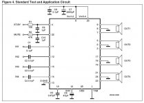
Hi all. I've been reading about chip amps and drooling. ") I love music, and making fairly simple electronics. For my first try, I'm making an amp for my fiancee, since we only have a head unit with pre outs available for her car. I decided on the TDA7386 because it seems to be the highest output 4 channel 12V single supply chip amp available. I have a few questions about the attached circuit diagram (the only one I could find besides the one in the datasheet):
I love music, and making fairly simple electronics. For my first try, I'm making an amp for my fiancee, since we only have a head unit with pre outs available for her car. I decided on the TDA7386 because it seems to be the highest output 4 channel 12V single supply chip amp available. I have a few questions about the attached circuit diagram (the only one I could find besides the one in the datasheet):
1. Am I correct to assume ceramic caps are used for C7, C10, C11 and C12?
2. Is a connection to power ground from signal ground (pin 10) really necessary? I'm worried about ground loops, although I understand that R9 would hopefully take care of that.
3. I would like to change the DC blocking caps on 2 of the inputs (C1 and C4) to raise the lower frequency cutoff. It states in the datasheet that 0.1uF has a lower frequency cutoff around 16Hz. I would like to raise that to somewhere between 50 and 80Hz, but I'm not sure what value the caps would then be.
4. Is the input impedance (5700 ohm?) suitable for my head unit? It has 8V 55 ohm outputs.
I love music, and making fairly simple electronics. For my first try, I'm making an amp for my fiancee, since we only have a head unit with pre outs available for her car. I decided on the TDA7386 because it seems to be the highest output 4 channel 12V single supply chip amp available. I have a few questions about the attached circuit diagram (the only one I could find besides the one in the datasheet):1. Am I correct to assume ceramic caps are used for C7, C10, C11 and C12?
2. Is a connection to power ground from signal ground (pin 10) really necessary? I'm worried about ground loops, although I understand that R9 would hopefully take care of that.
3. I would like to change the DC blocking caps on 2 of the inputs (C1 and C4) to raise the lower frequency cutoff. It states in the datasheet that 0.1uF has a lower frequency cutoff around 16Hz. I would like to raise that to somewhere between 50 and 80Hz, but I'm not sure what value the caps would then be.
4. Is the input impedance (5700 ohm?) suitable for my head unit? It has 8V 55 ohm outputs.
Attachments
How about the TDA7560? It is pin compatible, so you can use the same schematic and PCB and get 4x45W. Not that much more power, but significantly better distortion levels.Redshift187 said:I decided on the TDA7386 because it seems to be the highest output 4 channel 12V single supply chip amp available.
Should do the job.Redshift187 said:1. Am I correct to assume ceramic caps are used for C7, C10, C11 and C12?
Yes to both.Redshift187 said:2. Is a connection to power ground from signal ground (pin 10) really necessary? I'm worried about ground loops, although I understand that R9 would hopefully take care of that.
The formula is f=1/(2*PI*R*C). With f=16Hz and C=0,0000001F that gives R~100kOhms. That means you will need 33nF for ~50Hz and 22nF for ~80Hz.Redshift187 said:3. I would like to change the DC blocking caps on 2 of the inputs (C1 and C4) to raise the lower frequency cutoff. It states in the datasheet that 0.1uF has a lower frequency cutoff around 16Hz. I would like to raise that to somewhere between 50 and 80Hz, but I'm not sure what value the caps would then be.
Will work somehow. R1 through R8 however seem to be there for a connection to hi level outputs. They reduce the input level by a factor of ~5,75. Try to replace them with potentiometers 10k to 25k log. That brings the input impedance to a more practical level and gives you the possibility to adjust the sensitivity per channel like in any commercial amp.Redshift187 said:4. Is the input impedance (5700 ohm?) suitable for my head unit? It has 8V 55 ohm outputs.
Thanks so much guys. I will definitely use the TDA7560.
I'm using 4.5" coaxial front speakers,and 6.5" woofers in the rear. I'm not sure yet what frequency I'll high pass them at, maybe try 40Hz for the rear and 120Hz for the front. Which should be ~40nF and ~13nF respectively. I'll have to check the speaker datasheets to see what they can handle.
I'm using 4.5" coaxial front speakers,and 6.5" woofers in the rear. I'm not sure yet what frequency I'll high pass them at, maybe try 40Hz for the rear and 120Hz for the front. Which should be ~40nF and ~13nF respectively. I'll have to check the speaker datasheets to see what they can handle.
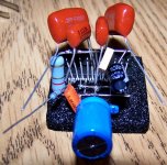
Well, the first step is done, I've soldered all components p2p. I used a TDA7560. Eleven in total. From the schematic above, I removed R1-R8, R11. I used an 8R2 for R9 because that's what I could get. For PS caps I followed the example circuit in the chip documentation and used a 2200uF and a 0.1uF. Input caps are 0.01uF for the front speakers, giving a cutoff around 150hz and 0.033uF for the rear speakers giving around 50hz cutoff. Now I think I have about 19 wires to solder for power and input/output.
Attachments
Hi there-can I make a suggestion or two?
1. You will definitely have to be prepared for bad ground loop noise on any DIY car audio design. You have to be prepared for to noise canceling circuits or ground isolation (ground loop isolators, for example).
2. It would be really beneficial to build it on a good prototyping board, and put it inside some type of plastic or metal enclosure so it's reliable and you don't have to pull over on the side of the road to troubleshoot it!
3. Add an input or gain control, as applicable, for each channel or the pair.
Sounds like a nice starter project-have fun.
Hi MartyM
I have an 8.2 ohm 2W resistor between the signal grounds and the power ground.
Too late to build it on a protoboard. But it works
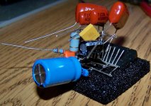
It's going in a small Hammond aluminum enclosure with lots of copper (it was cheap) heatsinking on the outside. I'll be putting a strain relief on the cables so they don't cause pins to move and short.
I have an 8.2 ohm 2W resistor between the signal grounds and the power ground.
Too late to build it on a protoboard. But it works
It's going in a small Hammond aluminum enclosure with lots of copper (it was cheap) heatsinking on the outside. I'll be putting a strain relief on the cables so they don't cause pins to move and short.
So I failed in my first attempt. First, I noticed that the schematic I posted has a mistake, the caps for SVR and AC-GND are switched. Not a big deal, but I had pop on turn on until I switched them. Also, after I swtiched them my DC offset dropped from ~40mV to unmeasureable.
That doesn't really matter though, as I'm pretty sure I toasted the IC. I accidentally hooked V+ up and ground to the standby pin. No big deal, except I forgot to hook ground up to ground. Got a nasty squeal for a second before I turned off the power. Now my output sounds like mute is enabled (sound, but barely audible when source is on max), and I've tried everything I can think of. I followed the reference schematic with the following exceptions: Mute pin is tied directly to V+ and the input caps are smaller values for some high-pass filtering. I checked voltages, I'm getting 11.5V at the chip. I tried putting a 47k resistor between the Mute pin and V+. I tried completely bypassing the input caps. I tried completely bypassing the input RCAs.
At this point I'm ready to scrap the project and start over, using MartyM's suggestion of using protoboard.
the other thing you might want to note, is with 12 volt input your only going to get around 15w output, maybe as high as 20w with an alternator running.
thats why car amplifiers in the 40+w range use switching power supplys to boost voltage
youll notice this in the datasheet for the TDA7386.
according to the datasheet, with 18v input you will get 35w output into 4 ohms at 1% THD.
thats why car amplifiers in the 40+w range use switching power supplys to boost voltage
youll notice this in the datasheet for the TDA7386.
according to the datasheet, with 18v input you will get 35w output into 4 ohms at 1% THD.
Actually I'm using the TDA7560, re: some messages near the top of the thread. Accordingly, it should put out 15W at 1% at 11.5V that I was testing with. I hooked up a 0.5W speaker, and it was still barely audible with the source at max volume (about 0.5V p-p). I was able to get decent volume only with 8V p-p source, but it wasn't loud enough for an automobile environment.
The front speakers I'm driving are fairly efficient, 35W 92dB sensitivity. Should be plenty of power. If I find I don't have enough power for the rear woofers, I'll make another amp just for them.
The front speakers I'm driving are fairly efficient, 35W 92dB sensitivity. Should be plenty of power. If I find I don't have enough power for the rear woofers, I'll make another amp just for them.
According to the datasheet the TDA7560 has a voltage gain of 26dB i. e about 20 times the input voltage. Your 0.5V input should have given you nearly 10V output, being 25W into 4 Ohm, if your power supply is up to it.
Did you check, if the mute and standby pins have more than 3.5V present?
Where did you measure the 0.5V? Directly at the input pins?
Did you try, if it works better, if you bypassed the input caps?
Did you check, if the mute and standby pins have more than 3.5V present?
Where did you measure the 0.5V? Directly at the input pins?
Did you try, if it works better, if you bypassed the input caps?
I didn't measure the 0.5V, I was taking it from the specs of my source. Yes I measured mute and standby pins. Standby works, it's not hooked up, so I was connecting and disconnecting it. Mute is tied to Vcc. The spec sheet says if mute is enabled, there's about 90dB attenuation. Which is what it sounds like, but mute should not be enabled. Oh, and yes I tried bypassing the input caps, among other things.
I now it is to late to discus about, but nevermind, here is my expirience with tda7386 as car amplifier.
I would like to use 7386 as power amplifier, and as preamp I used active crosover based on dr.Borivoje Jagodic TOCATA II system (http://bas.elitesecurity.org/mojiprojekti1.html) . Preamp worked very well, and if someone is interested i have my own pcb developed for it (cdr file, single layer, proved to work).
The basic idea is to have two 7386, two preamp boards, which gives 8 speakers, lets say, : 2 high, 2 midrange and 4 low speakers which should give very important sound pressure.
I managed to make one block (preamp pcb + power supply pcb with positive to negative voltage converter for op amps, and relays for overall power control + pcb with 7386)
For test, I used pioneer car cd player, atx power supply.
Hooked up everything, everything worked..BUT..
there is some little noise from power suply, and ground loop problem when conected signal in. Poweramp schematics is from original datasheet.
Then I used little transformators found on old modem PCI cards (1:1 similar) as ground loop isolator and they worked very well. Is there some other way?
Heatsink.
I 'm using heatsink from pentium IV processor, square one, and just realised that i need to cool it. Ok, PC Proccessor fan with some thermostat schematics will do the job, but when fan starts there is again a little noise hearing from speakers. Fan makes noise.
Ok, I know that you'll say why not to use passive cooling, say large heatsink and so on, but I don't know how large it should be. What is the minimum surface, and let's say that there is not maximum surface.
When I say little noise I realy mean little, but I would like to eliminate it.
For now, everything is on my workshop desk..need some time for car testing...wife, kids...job..., and yes..I'll post pcb-s, schematics and everything..as I sad before..need some time for real environement testings.
Someone with similar noise problems?
What kind of noise? Hum, buzz or hiss or..?strajo said:there is some little noise from power suply,
- Rework the grounding. Make separate grounds for signal and power. Connect them through a small resistor. Check for ground loops and interrupt them.strajo said:Then I used little transformators found on old modem PCI cards (1:1 similar) as ground loop isolator and they worked very well. Is there some other way?
- http://sound.westhost.com/earthing.htm
- Search the Forum. There are several threads dealing with ground loops.
Is that fan connected to the same power supply as the amplifiers? Then connect it to a different power supply.strajo said:I 'm using heatsink from pentium IV processor, square one, and just realised that i need to cool it. Ok, PC Proccessor fan with some thermostat schematics will do the job, but when fan starts there is again a little noise hearing from speakers. Fan makes noise.
Depends on the ambient temperature and the speaker impedance. The datasheet shows ~38 W power dissipation, when loaded with 4 x 4 Ohm. That means a heatsink with 1,2 K/W for 20°C and 0,7 K/W for 40°C. With 8 Ohm speakers the dissipation is more or less half that figure. There is a rule of thumb that says 10 cm² for each W of power dissipation, that would be 380 cm² for each of those TDA7386.[/B][/QUOTE]strajo said:Ok, I know that you'll say why not to use passive cooling, say large heatsink and so on, but I don't know how large it should be. What is the minimum surface, and let's say that there is not maximum surface.
thanks man for quick post.
I thing that my problem with earth loop is that I used same gnd points for sig gnd as for pwr gnd..I'll try adding small resistor, say 10 ohm.
Another thing, that cooling fan takes positive potential from regulated power supply (7812), and it's regulated 12V is used for preamp positive powering. (while lm2575t-12 is used for positive/negative converter for preamp op amps.).
Few minutes ago I solved its noise by adding 2200uF elektrolythic capacitor in paralel and 10 ohm resistor in series: fan - capacitor - resistor - positive.
I'll revork grounding, and I would ask you for opinion about Redshift187' s tda schematics from start of this post. That R9,10 ohm resistor...is it there for ground loop problems?
Other noise problems...that little noise from power supply is buzz and comes mainly from atx power supply fan...
I should put it all in car for real testing...I'll post results.
thanks again
R9 is the resistor that separates signal and power ground, the same you want to add.strajo said:I'll revork grounding, and I would ask you for opinion about Redshift187' s tda schematics from start of this post. That R9,10 ohm resistor...is it there for ground loop problems?
You won't get buzz in a car, because the power supply is DC. With a ground loop in a car you will get a howling noise that depends on the alternator speed (= motor rpm). Make sure that all audio equipment is grounded at the same point in the car and make the ground wire to the amplifier as thick as possible.strajo said:Other noise problems...that little noise from power supply is buzz and comes mainly from atx power supply fan...
I should put it all in car for real testing...I'll post results.
Believe or not, preamp circuit picks noise and feed it to TDA...no matter what to do, even adding R9 for separating sig gnd and real gnd, noise is still there. Somehow I burned my preamp, as so as that LM2575-12 used as -12v generator. But nevermind, after all...it is normal, when developing something I'll build new one..it is relatively cheap. Already have pcb..
Good news : when I removed pwr amp inputs, and power up only TDA, there is no noise at all.
So, remember those transformers from pci modem cards...I will surely remove them, and for RCA inputs, considering balanced line driver and receiver from http://sound.westhost.com/project51.htm.
What do you think..will that be helpful.
BTW, thanks for link..great site.
I'll build new one..it is relatively cheap. Already have pcb..Good news : when I removed pwr amp inputs, and power up only TDA, there is no noise at all.
So, remember those transformers from pci modem cards...I will surely remove them, and for RCA inputs, considering balanced line driver and receiver from http://sound.westhost.com/project51.htm.
What do you think..will that be helpful.
BTW, thanks for link..great site.
- Status
- This old topic is closed. If you want to reopen this topic, contact a moderator using the "Report Post" button.
- Home
- Amplifiers
- Chip Amps
- TDA7386 Car Amp