Has anyone compared the sound of a ( dual ) parallel LM3886 ( BP100 ? ) with a single LM3886 power boosted with complementary bipolar power transistors.
Cost wise and board space wise the parallel LM3886 is less expensive. As usual unless one builds both and compares them it isn't possible to say for sure if they do sound different.
I had tested a power Tr assisted LM3886 and it sounded fine though it measured poorer than a single LM3886. Never built a parallel LM3886 . Anyone done that and made any comparisons ?
Cheers
Note that the power transistor assisted chip can be done in at least two ways. You can sense load current in the output line or in the supply line. One way the transistors are in emitter follower mode and the other in common emitter mode with voltage gain.
Hi Routhun,
Yeah , if I did want more power the better way would be to go in for the newer chips. As it happens, I already have those !
However I was curious about how the different flavours of LM3886 implementation can sound.
Curiosity killed the cat ( LM3886?) . However I still want to know if anyone has tried this and compared the configurations.
Nothing to do with trying to get a very high output from a small chip. I'd put it down to experimentation.
")
Yeah , if I did want more power the better way would be to go in for the newer chips. As it happens, I already have those !
However I was curious about how the different flavours of LM3886 implementation can sound.
Curiosity killed the cat ( LM3886?) . However I still want to know if anyone has tried this and compared the configurations.
Nothing to do with trying to get a very high output from a small chip. I'd put it down to experimentation.
ashok said:Hi Routhun,
Yeah , if I did want more power the better way would be to go in for the newer chips. As it happens, I already have those !
However I was curious about how the different flavours of LM3886 implementation can sound.
Curiosity killed the cat ( LM3886?) . However I still want to know if anyone has tried this and compared the configurations.
Nothing to do with trying to get a very high output from a small chip. I'd put it down to experimentation.
Ah! I've been wondering about doing this to an LM1875, although I realize the voltage is low(ish) for accomodating output transistors. If there were a handy circuit with available parts I'd do it!!
Expectations:
Transistor output amplfies the sonic signature plus adds more from the transistors (better start off well).
Parallel does nothing whatsoever different except for cooler operating temperatures (cost savings on heatsinks is negated by additional cost of components).
Bridge meets the sonic signatures with equal and opposite force (potentially more enjoyable presentation for LM3886), plus a probable improvement on motor control (electronic dampening not as reliant on ground / power supply).
But, I don't know yet what happens in practice, except for parallel vs single chip.
I just built a parallel 3886 amp to power a pair of Dynaudio BM6 passive studio monitors.
It sound leagues better than a single LM3886, but that's probably because the single amp was poorly built, with all the grounds mixed up, and this new one also uses slightly better components and is pure dual mono. It's slightly better than the LM4780BPA which powers my main system.
I'm not even tempted to try a transistor-assisted chip-amp. Currently I have only my modded soundblaster rigged up to it (which is the poorest card I own) and the amp is doing magic with the Dynes.
Anyway the reason I posted here is that at the really low volumes I run most of the day, the amp actually runs warmer than a single 3886 everything else being equal. I guess because at those levels the amp is still working to balance both chips.
@Daniel: unclebob had written a wonderful reply to my question on floating grounds (bridged), you should dig it up to find exactly why it isn't such a great idea.
I have built both single (mono i.e 1 3886) LM3886 amps and bridged LM3886 amps (monoblocks - i.e 2 LM3886 chips in bridged configuration).
I would say that the bridged amps are gutsier than the single chip amps, but my speakers are so sensitive that it is difficult to say how they would sound into a 85dB speaker. I rigged up a soft clipping circuit to my LM3875 Gainclones to see how much power I was drawing on average. The lowest resistor setting suggested was for 5 Watts peak. I have adjusted the Resistor setting to about 1/2 - 1 watt peak, and the LED only flickers when I am being deafened.
I would say that the bridged amps are gutsier than the single chip amps, but my speakers are so sensitive that it is difficult to say how they would sound into a 85dB speaker. I rigged up a soft clipping circuit to my LM3875 Gainclones to see how much power I was drawing on average. The lowest resistor setting suggested was for 5 Watts peak. I have adjusted the Resistor setting to about 1/2 - 1 watt peak, and the LED only flickers when I am being deafened.
sangram said:@Daniel: unclebob had written a wonderful reply to my question on floating grounds (bridged), you should dig it up to find exactly why it isn't such a great idea.
Is that this?
http://www.diyaudio.com/forums/showthread.php?s=&threadid=119719
Well, whether its a good idea or not, its something good for learning. Actually, I'm wanting to bridge a pair of parallel amplifiers (parallel first, then bridge tied load). And, I'd like to compare that one to a "transistor assisted" amplifier.
I have no idea how to do this, and won't really know. . . until after its done.
Yeah, and it was unclejed, my bad.
The BPA I run is exactly what you want to do, it's basically two LM4780/channel, and each chip is run in parallel mode, and then the load is driven in a bridged config. I run it off a soundcard with a balanced output, so I don't need any bridging circuitry. If you don;t have such a card or source, you'll need a DRV134 or one of the simple bridging circuits from Rod Elliot's pages.
The BPA I run is exactly what you want to do, it's basically two LM4780/channel, and each chip is run in parallel mode, and then the load is driven in a bridged config. I run it off a soundcard with a balanced output, so I don't need any bridging circuitry. If you don;t have such a card or source, you'll need a DRV134 or one of the simple bridging circuits from Rod Elliot's pages.
speaking of rod elliot, here is what he says about running chips in parallel:
"While parallel operation is often recommended, I absolutely do not recommend that you run the amps in parallel. There are very strict requirements for gain tolerance for parallel operation - typically the amplifiers should be matched to within 0.1% or better over the entire audio bandwidth and beyond. Because of the very low output impedance of the ICs, even a mismatch of 100mV (instantaneous, at any voltage or frequency) will cause large circulating currents through the ICs. While 0.1Ω resistors are usually suggested, a 100mV voltage mismatch (0.15% at a peak voltage of 60V) will cause a circulating current of 0.5A. This causes overheating and will invoke the wrath of the protection circuits."
this is taken from:
RE page
i have some lm4780's running in parallel. they do run warmer than my other single chip amps. i guess this could be the reason. however, the protection circuitry is definitely not being activated as i have checked with a scope.
I agree with Rod about the circulating current, and my experience bears it out.
But there's no way I'm going to be able to drive a pair of Dynes with a chipamp if I don't parallel them up. A single-ended amp runs out of steam too quickly.
The protection is absolutely not kicking in, and the amp is gutsy enough for the speakers. It runs a little warm at lower loads, but there's enough heatsinking and the temps don't cross 50 degrees anyway. At higher loads it actually runs a mite cooler, maybe the chips equalise at more typical power levels.
I did use slightly higher resistor values for the parallel operation. I stuck to two 0.47ohm resistors per chip, bringing the resistance to 0.2 ohms per chip. This is slightly higher than the recommended 0.1 ohm, and while it may affect the damping factor, it helps because of the mismatch through the rest of the chain (I did not hand-match resistors or chips).
@ashok, do you have some references I can look at? I'm struggling with a peculiar problem where I might need a high power output from just one channel in a multichannel system, and might need to resort to transistor assistance. I do know the basic principles but can't locate a reference anywhere.
TIA
TIA
You cannot get more power out from the chip using outboard transistors. That is already limited by the power supply limitations. All it will do is share the power dissipated and since the transistors can provide extra current it can handle lower impedance loads but without the benefit of any protection for the external power devices.
It is interesting to note that even in this configuration , the power dissipation of the chip is still fairly high. Check out the output vs power dissipation curves.
Look up the TDA2030 application data sheet.
Cheers.
Edit : Power output is higher with 4 ohm loads when the power transistors start sharing the load. However you have to be careful how the power is shared. I have tried this scheme but there is no audible improvement except that the chance of the spike protection kicking in on impedance dips is reduced or eliminated.
As usual you always pay a price !
Exactly my thinking - I was planning on a lower impedance load on the .1 channel (eminently possible with two drivers) to coax a little more grunt out of the chip (it's a 4781). There's usually enough voltage available from a chipamps output to push some pretty serious power, but they're always limited by output current.
The power supply need not be limited to a lower output, it can be configured for the increased load. I'm looking at the TDA2030 datasheet, unfortunately it uses the voltage gain topology. Which is necessary, as the TDA2030 has a very small voltage swing on the output. I was hoping you had a schematic for the emitter follower topology.
Thanks anyway.
Here is the circuit I tried .
I did not use the resistors R2 and R3. I'm showing it because some implementations include it. I can't find the files that I downloaded long ago. So I've made a quick sketch of the output stage in EF mode. Selecting the value for R1 is simple and depends on which point you want the power transistors to start turning on. The resistor will carry the full load current and so you need to determine its power rating ( I^2 x R ).
I did not use the resistors R2 and R3. I'm showing it because some implementations include it. I can't find the files that I downloaded long ago. So I've made a quick sketch of the output stage in EF mode. Selecting the value for R1 is simple and depends on which point you want the power transistors to start turning on. The resistor will carry the full load current and so you need to determine its power rating ( I^2 x R ).
Attachments
Darlingtons would be useful if you need to operate with lower base drive currents. Here you are dealing with an output with very low impedance and capable of driving very low loads. Your base current will be negligible even with a normal bipolar power transistor.
The other factor against the darlington is that the Vbe drop that you loose will increase ( two BE junctions). It may not cause any audible reduction in power output , but you will certainly get less unclipped output with a Darlington.
The other factor against the darlington is that the Vbe drop that you loose will increase ( two BE junctions). It may not cause any audible reduction in power output , but you will certainly get less unclipped output with a Darlington.
Originally posted by ashok <snip> less unclipped output with a Darlington. [/B]
I guessed as much.
I need a very early turn-on threshold, as the 4781 has very poor current limit - 3 amps, so I was thinking of a 1 ohm resistor. This will cause a very significant drop (turn-on at 1.4A for two vbe, and 0.7A for one transistor), and if it wasn't a darlington the transistors would turn on even earlier, which is counterproductive to me. I could put in a 2-ohm resistor, but that would cause too much distortion when the opamp was operating alone. As it is 1 ohm is too high for my taste.
Thanks, I now need to start planning the build.
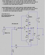
ashok said:Here is the circuit I tried .
When output level is low, Q1 and Q2 are off. The output current is solely provided by the chip amp. When Q1 and/or Q2 is on, the output current is the sum of chip amp and Q1/Q2. The overall circuit current gain changes and gm-doubling seems to be happening here.
I simulated the circuit in LTspice. The opamp is an ideal one. THD performance for feedback sampling point taken at A or B was simulated. As we expected, THD is lower for taking feedback at point B. There is no gm-doubling effect observed. The output current of the opamp decreases when either Q1 or Q2 turns on. Hence, the overall amplifier current gain does not change. Using this simulator, we can easily estimate power dissipation on each component. R7 and R8 model PCB track resistance. As pointed out in Self’s book (distortion #7), feedback taken at either S1 or S2 degrades performance. Theoretically, we should take feedback at the load terminal (speaker input post). I think Kenwood tried this in the 80’s.
Attachments
- Status
- This old topic is closed. If you want to reopen this topic, contact a moderator using the "Report Post" button.
- Home
- Amplifiers
- Chip Amps
- Parallel or Transistor assisted chip amp ?