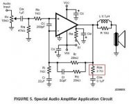
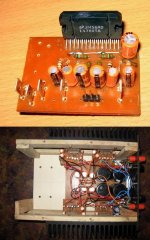
I wired an LM4780 amplifier as per the special amplifier circuit mentioned in NS LM4780 datasheet. picturs are enclosed.
After making the PCB i connected it to an audio source and speakers and appplied +-25 vDC and it worked fine.
Now today when i assempled it in the body of amplifier and just applied DC voltage (+-25 V). The output zobal resisters "Burnt Off" in the first second. immediately i switched off the supply and checked the ICs, visually OK. But the Zobal resistors were completly burnt.
Now i Did not connected any source or speaker to the amplifier. -> IS that may be the reason that resistor "Rsn" burned off??
please comment, all the four modules of LM4780 are down..
Attachments
The Zobel resistor would burn if you had RF oscillations.
Short the inputs to ground and test again .
Never power up all channels at the same time on a new build.
If something was wrong they would all blow up , like here !
Reconnect one channel ( Disconnect all other channels.)
with a good Zobel resistor and short input to ground and power up. If it still burns up , you need to check everything again.
If it's OK , you will need to make it stable with an open input socket .
After checking if it's stable with an open input socket , add another channel and re-test. Add other channels one by one , just in case some wiring loop on any channel is causing instability.
Cheers.
Hi,
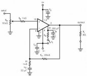
fig 5 is a good circuit to build and it usually avoids the worst of the problems that the fewer component circuits have.
BUT,
the three grounds on the left hand side are all INPUT grounds.
The five grounds on the right are power grounds. Be very careful that your layout does not mix these up.
It is very confusing when most use the same word (ground) and the same symbol, but they intend different things. The builder has to interpret what he/she sees and assemble accordingly. Amp building is a thinkers hobby, don't expect to jump in and achieve consistent success unless you make the effort to understand what it is you are trying to build.
Did you install both the electrolytic and the nonpolar parts of Cs?
How close to the supply pins are the nonpolar caps?
the 2.7 ohm resistor should be 2W. I don't see the 0.1uF cap in series.
That particular design should be oscillation proof.
Looking at your pix I think that you have to consider the lead dressing which is a nice way of saying that you should get some tie wraps and neaten it up a bit. If you can't find tie-wraps you can use short lengths of radio shack or CAT5 wire to hold the wires together. The power leads can pick up Radio Frequency Interference and kick the amp chip over into oscillation. You are running a gain of 21 so the chip-amp will do a very good job of picking up RFI.
Make sure that the chipamp is isolated from the heat sink with a mica or Berqquist (insulated) washer -- and the heat sinks should be tied together and connected to ground. Elsewise they are just another surface which picks up electromagnetic radiation.
Put 100nF/50V ceramic caps at each power supply pin to ground.
I don't see where you have put in the 200pF cap between the inverting and non-inverting inputs...
Well, i guess the high freq oscillations damaged the zobal resistors, coz the same thing ws working when input and speakers were connected.
i am putting new resistors and try again tomorrow. here's the pcb layout and the signal ground and power ground are joined by 10 ohm,1W resistance
i am putting new resistors and try again tomorrow. here's the pcb layout and the signal ground and power ground are joined by 10 ohm,1W resistance
Attachments
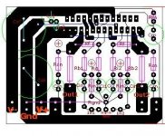
2caps and a resistor are missing between the PCB layout and the schematic.
the assembled PCB has even more missing.
When you replace the burnt resistors, do not connect the speaker.
Use a bulb tester to connect the transformer to the mains and short the input to signal ground.
switch on and measure the output offset.
the assembled PCB has even more missing.
When you replace the burnt resistors, do not connect the speaker.
Use a bulb tester to connect the transformer to the mains and short the input to signal ground.
switch on and measure the output offset.
AndrewT said:2caps and a resistor are missing between the PCB layout and the schematic.
the assembled PCB has even more missing.
just let me clear. Cr & Rf2 are Not there in PCB (and these are optional component - won't hinder the basic functioning). Rin &Cc are located on lower side of PCB (though i have not provided holes for putting Cc i n PCB).
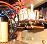
AndrewT said:where's L & R.
is there anything else missing?
 sorry not to mention them.. They are also on the other side of PCB, and the resistor is inside the inductor coil.
Attachments
the 2.7 ohm resistor should be 2W
According to the datasheet 1/4W is enough. A 2W resistor will cure the symptom, but not the disease. It might however swap the symptom from the resistor to the 0,1µF capacitor until the disease is cured.
pacificblue said:
According to the datasheet 1/4W is enough. A 2W resistor will cure the symptom, but not the disease. It might however swap the symptom from the resistor to the 0,1µF capacitor until the disease is cured.
From practical experience I will stick with 2W.
With the loop compensation, inductor and snubber this design shouldn't oscillate...but you can thermally cycle the Overture chips pretty quickly (and destructively).
Will it damage IC ??
In the Basic circuit Layout for LM3886 and LM4780 given in "National Semiconductor", they have not shown the zobal network.
So, is it safe for the IC if zobal resistor & cap is not there? and what if the speakers are not connected?
Coz i plan to make 8 channel amplifier but only 4 will be working. But I plan to apply DC power to all 8 channels and seal the enclosure.
Will it be OK if no input and no output is connected and still apply Vcc to each LM4780 module ?
Attachments
got 'my' solution
- what i found is that for my particular layout, even if a half feet wire is connected to input connectors@PCB results in stable system (zobal resistor won't burn).
But if i don't conenct anything to input connectors right on the PCBs, the zobal resistor burns even if speakers are conencted. mmm i don't know whether the problem is particular to this layout (that i'll be going to optimise a litle bit) or exists normally (till not experienced). Anyways i got my solution.
- what i found is that for my particular layout, even if a half feet wire is connected to input connectors@PCB results in stable system (zobal resistor won't burn). But if i don't conenct anything to input connectors right on the PCBs, the zobal resistor burns even if speakers are conencted. mmm i don't know whether the problem is particular to this layout (that i'll be going to optimise a litle bit) or exists normally (till not experienced). Anyways i got my solution.
Hi, from the symptoms described sounds like a case of classic HF oscillations. You can check with a O-scope if you have one, could be up around 1MHz or so.
For a quick test try adding 2 decoupling caps close to the power IC supply pins, try a couple of good 0.1- and 10uF caps to each rail.
For a quick test try adding 2 decoupling caps close to the power IC supply pins, try a couple of good 0.1- and 10uF caps to each rail.
If a small length of cable at the input stops the oscillations it means you need to connect a capacitor at the input.
An average shielded cable has about 100pF per meter capacitance , so you can connect a 33pF or 47pF cap from input to ground. You could also add a series resistor of 1 k ohm from input to source. That would roll off the HF beyond 20 Khz.
Would you have any problems now ?
An average shielded cable has about 100pF per meter capacitance , so you can connect a 33pF or 47pF cap from input to ground. You could also add a series resistor of 1 k ohm from input to source. That would roll off the HF beyond 20 Khz.
Would you have any problems now ?
ashok said:If a small length of cable at the input stops the oscillations it means you need to connect a capacitor at the input.
An average shielded cable has about 100pF per meter capacitance , so you can connect a 33pF or 47pF cap from input to ground. You could also add a series resistor of 1 k ohm from input to source. That would roll off the HF beyond 20 Khz.
Would you have any problems now ?
Thanx - This is the exact solution.... these were missing in my circuit..
- Status
- This old topic is closed. If you want to reopen this topic, contact a moderator using the "Report Post" button.
- Home
- Amplifiers
- Chip Amps
- lm4780 Zobal resistor burns immediately on Power ON