I'm just testing out my 24 step stepped attenuator to the front of my chipamp gainclone. http://cgi.ebay.ie/Attenuator-24-Step-10K-A-Dale-resistor-Stereo-NEW_W0QQitemZ220247489309QQihZ012QQcategoryZ73369QQtcZphotoQQcmdZViewItemQQ_trksidZp1742.m153.l1262
It's wired up on my bench with crocodile clips and running from a bench supply.
I'm getting a small 'pop' when the pot is turned. Is there anything that can be done to remove this ? (I know it could be just the poor connections - the croc clips)
thanks
It's wired up on my bench with crocodile clips and running from a bench supply.
I'm getting a small 'pop' when the pot is turned. Is there anything that can be done to remove this ? (I know it could be just the poor connections - the croc clips)
thanks
well it turns out it was a dodgy ground 
i do have another newbie question though.
I'm using a 10k volume control with a 25Vac input per channel (so around 32Vdc once rectified and with diode losses ?)
The 10k has a very bad scale. The first click is a big step while the other 23 make very little difference to the volume.
Do i simply need a larger input pot resistance to adjust the scale? Or can i use maybe an in series resistance to help set the volume scale ?
well it does attenuate the signal so i'm assuming ") angel: ) it is wired correctly, its just not very linear and most of the 'steps' i can't hear the attenuation (though i can see it on the scope).
angel: ) it is wired correctly, its just not very linear and most of the 'steps' i can't hear the attenuation (though i can see it on the scope).
A normal 10k pot does a better job to be honest. Would you suggest i try the 50k or the 100k 24 step ?
angel: ) it is wired correctly, its just not very linear and most of the 'steps' i can't hear the attenuation (though i can see it on the scope). A normal 10k pot does a better job to be honest. Would you suggest i try the 50k or the 100k 24 step ?
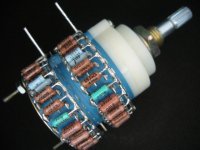
Ted, your 10K attenuator will have 24 voltage dividers that consist of two resistors, one in series, and one to ground that divide the signal and shunt the unwanted part to ground.
The total value of the resistors in each pair will add up to the value of the attenuator - 10K (10,000 ohms) in your case.
If one of the resistor values is 100K as Peter points out from the picture of your attenuator, then the attenuator cannot be 10K.
The total value of the resistors in each pair will add up to the value of the attenuator - 10K (10,000 ohms) in your case.
If one of the resistor values is 100K as Peter points out from the picture of your attenuator, then the attenuator cannot be 10K.
just take some rest ... then ... seat down ... then ... measure each restistance for each step ... then enter the values into excel and compare both channels with the resulting graph ... this all takes about 10 minutes to get an oversight about what you are holding in your hands ... and it let's you avoid troubles before you solder a part into a circuit

Ted205 said:here is a graph of the output resistance. As you can see steps 16-24 are wasted.
AndrewT said:Hi,
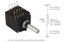
you have the attenuator wired up wrong.
The return side should be common to both the input and output.
I think you have wired it up as a variable resistor instead of an attenuator.
It looks like input and output connections from attenuator are mixed up.
Attached is a graph showing proper way to a wire a pot. You can see that at lowest setting, the output resistance is zero and then goes up and the input resistance is fixed, equal to pot value.
If you wire your attenuator this way, it should work fine.
Attachments
- Status
- This old topic is closed. If you want to reopen this topic, contact a moderator using the "Report Post" button.
- Home
- Amplifiers
- Chip Amps
- stepped attenuator pop