Hello
The other day i noticed that my guitar amplifier enetrs distortion at sound levels much lwoer than i expected. So i conencted it to an oscilloscope and noticed that clipping started at around +-24V. I am using a 28V 300VA toroid transformer with 4700 uF caps for each suplly rail and measured the dc voltage as 40.7V at idle. On datasheets this lm3886 has a typical power of 50W into 8 ohms at +- 35V suplly. I am using the standart typical application circuit that is listed in lm3886 datasheet except the output inductor, capacitor, etc. (im very disappointed with lm3886, its expensive, its inefficent, it has audible backgroud noise!)
I checked the LM7290s datasheets the otehr day and noticed that they are much more efficient than lm3886, they are cheaper and they probably sound as good as lm3886. Problem is they dont have a simple circuit as the lm. I read a few articles in forum and in the datasheets it was written that the tda7293 could suplly around 100W of power at +-40V which is my suplly at hand. Problem is it says it cannot handle this power due to dissipation limits. I also saw people blowing this chip instant they put the power on. This chip also has soem mute, standybye functions (i dotn want to use them and i want to completely get rid of all components associated with them) and 2 seperate suplly rails.
I want to simplify the typical application circuit (at least no mute-standbye stuff) and make the bypass caps closer to the ic. What modifications can i make over the typical application circuit? If i simply not conenct the mute-standby pins to anywhere, will it work fine or burn etc? Also i will suplly this unit with around 40V dc with 4700uF caps at each real. the gain of my preamplifier is large enough to put the lm3886 into distortion, which emans this chip may run at 70-80W constantly at full power. can a heatsink - fan etc handle all this? Or there is no way that i can use a single 7293 to run at 80W power continuoisly.
Thank you for your help.
I would up the supply to 2 x 4700uf per rail as a minimum.
For your application I recommend the trusty old LM3875... no mute pins to deal with, can live at 40VDC provided you have good heatsinking... can deliver adequate power into 8 ohms...
I would make the high pass filter quite high to save the amp from dealing with power wasted on low frequency harmonics...
I do not think any chip can live at a sustained 80W output...
There is no need for that amount of power anyway unless it is for large or outdoor venues... 1 Watt can drive a speaker to full output, WHAT that output is depends on speaker efficiency....
There are many high efficiency, low power guitar speakers available, even the famous Celestion 30 is.. well, a 30W driver... way loud though.
I recently Built a couple amps based on the TDA7293, I also couldn"t find a PCB design so i finally just broke down and used the PCB design in the datasheet but modified it a bit so that the Mute/standby was disabled...It does make a little pop when you start it up but it isn"t bad...I don"t notice any real hum or noise useing the Datasheet PCB design....
I used them with a Bi-amped bass guitar amp, I have a 12db/oct Low pass filter on one channel for the Sub set at 400hz and a high pass filter on the other for the driver and a Volume controll on each so I can tune it how much of the sub and/Or driver I want....
I allready have the TDA7293 PCB done up in MS Paint so if you want to try it let me know and I"ll post it for you.....
Cheers
ý will also try lm3875, which i just checked teh datasheet and surprisingly it is more powerful than 3886 (40w min vs 30w min, 56w average vs 50). i will immeaditly swap the 3886 with 3875 and put 2 more 4700 uF in parallel to psu. Thank you for the advices.
also the amp gets in distortion at around frequencies 100-150w which i believe the guitar produces the strongest output at those frequencies and the total amplifier sounds as if it has much base indeed. shall i decerase the input cap (1uF with a 470n or 220n one) or i used a 10uF at negative feedback path in junction with a 330 ohm resistor (22k between output and inverting input pins). shall i reduce the 10u F electrolytic to a 1uF polyfilm etc?
also the amp gets in distortion at around frequencies 100-150w which i believe the guitar produces the strongest output at those frequencies and the total amplifier sounds as if it has much base indeed. shall i decerase the input cap (1uF with a 470n or 220n one) or i used a 10uF at negative feedback path in junction with a 330 ohm resistor (22k between output and inverting input pins). shall i reduce the 10u F electrolytic to a 1uF polyfilm etc?
weatherlight said:shall i decerase the input cap (1uF with a 470n or 220n one)
That's a good start on getting rid of some clipping. The 470n is the one I use for popular music with my LM1875. Although it doesn't clip, it does have a 4 amper limiter. The speakers I used for its projects are 8" and 6" and they are 4 ohms. So, I simply had no need of sending signals that didn't come out of the speakers. 😉
Its now able for more than twice the output, without setting off its limiter. The limiter on LM1875 makes abrupt "blanks" of silence. In my usage, that's more polite than the alternatives. . .
On the larger NatSemi chip amps, lm3875 and lm3886, the spike system can make some terribly loud clipping; however, the combination of sufficient power and a "right sized" input filter cap, should help considerably.
On the very powerful ST chips, TDA7293 and TDA7294, they're prone to overamplifying even order harmonics, especially at around 70hz, and can sound much like a jukebox. The simple cure is to "right size" both its NFB cap and "right size" its input filter cap. However, their interesting character could make for a nice "warm" guitar amp, and there's no shortage of power output.
I just checked the modular application of the tda7293 in the datasheets. It seems simple (much simple than the high efficiency one). Will the modular application be suitable for the +-40V and the gain capable of reaching 80-100W? Also i noticed many people dont like the sound of electrolytic caps (22uF etc) in amplifiers. I should use a 47u at bootstrap and probably something around 5-10u at NFB. Is there a non electrolytic cap at that size or a good quality one? (the ones i can find around here are mostly standart cheap caps)
weatherlight said:I just checked the modular application of the tda7293 in the datasheets. It seems simple (much simple than the high efficiency one). Will the modular application be suitable for the +-40V and the gain capable of reaching 80-100W? Also i noticed many people dont like the sound of electrolytic caps (22uF etc) in amplifiers. I should use a 47u at bootstrap and probably something around 5-10u at NFB. Is there a non electrolytic cap at that size or a good quality one? (the ones i can find around here are mostly standart cheap caps)
Bootstrap, 47uF is right.
NFB, 10uF to 22uF, but not larger
Electrolytic caps do come in "made for audio" varieties.
Power? Do you have 4, 6, or 8 ohm speakers? What is the lowest desired frequency response? What is the LF rolloff of the speaker?
I need a 3db cutoff around at most 70Hz or so. I believe the low e string gives 82 Hz at 0 fret position. I have a 12" 8 ohm 100w guitar speaker. Problem is, i plotted out the mid band frequency range and the preamp-equalizer-poweramp total 3db response was already something like 60Hz-4kHz. i can degrease the input 1uF cap with 470nF and the 10uF cap with something a bit smaller but if i go beyind that the low e string will fade abit 🙁
weatherlight said:thank you, a pcb without mute standbye stuff will be very helpful 🙂
Here is the Version of the PCB that i did from the Layout in the datasheet..
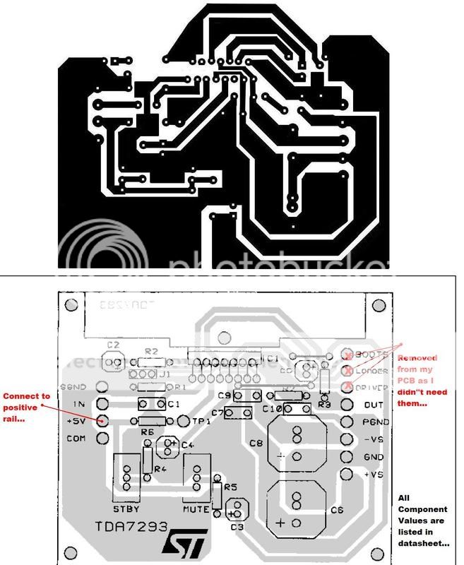
As you see I got rid of a couple features as i didn"t need them for my amp, mostly just the Bootstrap feature which i wasn"t going to use as my supply Voltages were +/- 42V DC, and the Mute/standby feature is disabled...I also increased the track thickness and the overall size of the Traces and planes....
I hope you can use it....
Cheers
We could, perhaps, fool it a bit. Try Nichicon Muse 0.47uF for your input filter cap.
And, just leave the NFB cap at values between 22uF and 10uF (probably you already have one of those installed). However, make that one a Nichicon KZ or Elna's Cerafine.
Substitute: You can add (parallel) a 4.7nF or 10nF, polyester (bubble) or ceramic, to a rather ordinary (22uF or 10uF) electrolytic cap for nearly-similar results. When using an ordinary power electrolytic cap in that role, make it a high voltage capacity model.
Additional experiment: Get some very cheap polyester caps at 5x smaller and 50x smaller than estimated values for electrolytic. For instance, you parallel the "5x smaller" with the "50x smaller" cap.
Well, there's some stuff to try.
P.S. If none of this works, then we need to look at the whole circuit and see if there's an impedance mismatch.
paralleling the 10-22uF electrolytic caps with a 100nF or so does something similar to supply bypassing with 2 caps (100nF and 100uF etc)?
Also i'm planning to built the modular application circuit in the datasheets (since one tda will probably burn at 40V suplly with maximum gain, (100w). Do i need like 10000uF caps at power suplly and another 1000uF at tda suplly bypass?
Also i'm planning to built the modular application circuit in the datasheets (since one tda will probably burn at 40V suplly with maximum gain, (100w). Do i need like 10000uF caps at power suplly and another 1000uF at tda suplly bypass?
weatherlight said:paralleling the 10-22uF electrolytic caps with a 100nF or so does something similar to supply bypassing with 2 caps (100nF and 100uF etc)?
Also i'm planning to built the modular application circuit in the datasheets (since one tda will probably burn at 40V suplly with maximum gain, (100w). Do i need like 10000uF caps at power suplly and another 1000uF at tda suplly bypass?
I've just got two thing to say.
If an electrolytic cap is "made for power" then its probable that you can get good results from bypassing it with 100nF or smaller (or much smaller).
When you have a big offboard power supply, then the onboard (at amplifier) caps are usually smaller, say in the range of 330uF, and this is especially true of monobloc/dualmono layouts.
weatherlight said:paralleling the 10-22uF electrolytic caps with a 100nF or so does something similar to supply bypassing with 2 caps (100nF and 100uF etc)?
Also i'm planning to built the modular application circuit in the datasheets (since one tda will probably burn at 40V suplly with maximum gain, (100w). Do i need like 10000uF caps at power suplly and another 1000uF at tda suplly bypass?
Hi There,
I'm curious about what Mr Ionomolo was says here :
http://www.diyaudio.com/forums/showthread.php?s=&threadid=118919&perpage=25&pagenumber=2
as you also mention, i think the 1000uF he mentioned is on PCB / before the 100/220/330/470uF. our local KIT suplier also 'always' add a pair of 1000uF on their chipamp PCB ( TDA7293, 7294, lm1875, 3875, 3886 etc ) but none 1000uf for their BJTs PCB.
i think its for a good technical reasons than just sale the 1000uFs. they're cheap anyway.
Mr Ionomolo,
need yor kindly explanation and advs...
Brgds
Eka
Nordic said:The experiment is cheap, the lessons priceless.. give it a try.
I just runs test for having a suitable lowpass input caps by compares 4 caps.
2 kind of polarized Electrolit and 2 other non/bipolar film caps. all 4.7uF.
the result : unlike the films. the electrolitycs a bit keep the sounds ( bass, kick bass, lower sound ) longer. the extra resonance is not good for sub woofer, we need the beat/ the speaker's cone reverse ontime. and join the stereo's sound naturaly/harmonicly.
that's may offtopic, only report tht : vary caps, same value, brands, may vary the result. n this 2 vs 2 may not enough to judge. except my personal define 😀
my best choise for guitar amp ( 83Hz-880Hz is 2.2uF filmcaps / MKP 10 without additional smaller for bypass. ) on C input, and 22uF nonpolar at Ci for 2 x LM3886 / 2 x 10' fullrange.
get your best😉
our local KIT suplier also 'always' add a pair of 1000uF on their chipamp PCB ( TDA7293, 7294, lm1875, 3875, 3886 etc ) but none 1000uf for their BJTs PCB.
Hi eketehe
I was wondering can you give the your local kit suplier addres/phone, is it bandung or jakarta ? and how much it's cost for lm 1875, I've been searching lm1875 kit at glodok but no luck thank
Hi eketehe
I was wondering can you give the your local kit suplier addres/phone, is it bandung or jakarta ? and how much it's cost for lm 1875, I've been searching lm1875 kit at glodok but no luck thank
my local suppliers tell me lm3875 is obsolete and i cant even find the lm3876 around here. is there a way i can find them or is it really obsolete 🙁 ?
bedil said:our local KIT suplier also 'always' add a pair of 1000uF on their chipamp PCB ( TDA7293, 7294, lm1875, 3875, 3886 etc ) but none 1000uf for their BJTs PCB.
Hi eketehe
I was wondering can you give the your local kit suplier addres/phone, is it bandung or jakarta ? and how much it's cost for lm 1875, I've been searching lm1875 kit at glodok but no luck thank
Hi Bedil,
Ok i'll send you a PM.
Brgds.
Eka
weatherlight said:my local suppliers tell me lm3875 is obsolete and i cant even find the lm3876 around here. is there a way i can find them or is it really obsolete 🙁 ?
Dear weatherlight,
1- Do I know you?
2- If I dont know then why dont you join us also?
Who we are; forum.diyaudiotr.com
3- LM3875 is not recommended for new designs. Thats true, but it is NOT OBSOLETE. I think its the best sounding chipmap. And I am currently worlking on a LM3875 project for over one month.
4- You can find LM3875 from Farnell, Digikey and the other suppliers, may be you can request samples from National Semiconductors.
- Status
- Not open for further replies.
- Home
- Amplifiers
- Chip Amps
- need help with TDA7293