Hi,
I recently started studying amp design and theory and all that, so I'm still a little behind on probably a lot of what I should know before attempting a project like this (even if it is simple), but I figure the only way i'm going to learn is to try.
i've been wanting to build a phono preamp for a while....mostly because the only preamp i have at my disposal is in my massively heavy Denon pre/mains amplifier and there have been times I've wanted to take my turntable and my "portable studio" over to someone's house to "rip" thier vinyl (for the times they won't let it leave the house).
I've looked at a BUNCH of various schematics, but I wanted something that was rather simple, small, and rather high quality...preferable with the ability to turn on or off RIAA EQ curve.
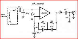
I was looking through a service manual at work for one of the early 90's Rowe jukeboxes. While the book was for a CD-box..they were also still making vinyl boxes at the time and used pretty much the same amplifier...so it had the phono preamp section still included..and making a quick diagram, got the basic design on paper so i could play around with it later.
As it stands in the schematic, the thing used an LM833 and only 12 other parts (although I think i can lose my 100K resistor on output since i'm not feeding it into the EQ circuit)
I've read all kinds of various articles and posts about the LM833...some good, some bad. My question is pretty much two-fold. A) is this design even any good for a standalone amp? I can run it through virtural insturments all day but that won't tell me much and B) if the LM833 is not a good choice for the job, what others would you all reccommend.
The main reason i want to go with an opamp and not discreet transistors is a size issue, i can probably both channels of this amp on a board much smaller than if i did transistors, which, size is of importance.
I can't honestly say i know what the gain factor is (but will probably figure that out later on in the evening as i get further into the documentation i've got)...but in my mind i figure i can calculate what i need later.
The schematic for the amp is here: http://img504.imageshack.us/img504/2779/roweschematicfz3.gif
few things: i know the layout is horrible, it's difficult getting the program to do things EXACTLY how i want them..VCC says 5v but that's not what i intend on running the amp at (more like 12 or 18), but when i took that shot i hadn't fixed it..and i left some of the virtural test equipment laying there. i've already figured out that by removing C3 and C5 it effectively kills the RIAA curve (at least the scope shows it would)
I do however really love this design because of it's apparent simplicity. It isn't over-engineered and, I've heard Rowe vinyl boxes that use this same circuit...they do sound quite nice.
I'm open for any and all suggestions and critisims...this has always been a hobby of mine and I'm just starting to get serious about it...so i'm willing to learn.
thanks
-jay
I recently started studying amp design and theory and all that, so I'm still a little behind on probably a lot of what I should know before attempting a project like this (even if it is simple), but I figure the only way i'm going to learn is to try.
i've been wanting to build a phono preamp for a while....mostly because the only preamp i have at my disposal is in my massively heavy Denon pre/mains amplifier and there have been times I've wanted to take my turntable and my "portable studio" over to someone's house to "rip" thier vinyl (for the times they won't let it leave the house).
I've looked at a BUNCH of various schematics, but I wanted something that was rather simple, small, and rather high quality...preferable with the ability to turn on or off RIAA EQ curve.
I was looking through a service manual at work for one of the early 90's Rowe jukeboxes. While the book was for a CD-box..they were also still making vinyl boxes at the time and used pretty much the same amplifier...so it had the phono preamp section still included..and making a quick diagram, got the basic design on paper so i could play around with it later.
As it stands in the schematic, the thing used an LM833 and only 12 other parts (although I think i can lose my 100K resistor on output since i'm not feeding it into the EQ circuit)
I've read all kinds of various articles and posts about the LM833...some good, some bad. My question is pretty much two-fold. A) is this design even any good for a standalone amp? I can run it through virtural insturments all day but that won't tell me much and B) if the LM833 is not a good choice for the job, what others would you all reccommend.
The main reason i want to go with an opamp and not discreet transistors is a size issue, i can probably both channels of this amp on a board much smaller than if i did transistors, which, size is of importance.
I can't honestly say i know what the gain factor is (but will probably figure that out later on in the evening as i get further into the documentation i've got)...but in my mind i figure i can calculate what i need later.
The schematic for the amp is here: http://img504.imageshack.us/img504/2779/roweschematicfz3.gif
few things: i know the layout is horrible, it's difficult getting the program to do things EXACTLY how i want them..VCC says 5v but that's not what i intend on running the amp at (more like 12 or 18), but when i took that shot i hadn't fixed it..and i left some of the virtural test equipment laying there. i've already figured out that by removing C3 and C5 it effectively kills the RIAA curve (at least the scope shows it would)
I do however really love this design because of it's apparent simplicity. It isn't over-engineered and, I've heard Rowe vinyl boxes that use this same circuit...they do sound quite nice.
I'm open for any and all suggestions and critisims...this has always been a hobby of mine and I'm just starting to get serious about it...so i'm willing to learn.
thanks
-jay
Hi,
That circuit as it is will not work ! Pin 3 has to be biased to mid supply ( for a single rail design ) for one thing. Have a look at this for the LM833. This needs a dual (split) supply which can be either a pair of PP3's or a single supply with a further OpAmp to create it.
Regards Karl
Edit, The LM833 is (was !) considered very good in it's day. I would probably go with an OPA2604 or similar, although a FET input OpAmp may not give as low a noise figure at these impedances. If you are running of batteries choose one with a low current consumption. A TL072 is probably perfect if you are only ripping to MP3. Arghhhhhh.
Attachments


I guess you have Multisim as that's what you've used for the schematic -- save yourself a lot of time by using the Transfer Function Block from the "Controlled Functions" components -- set up the polynomial variables as the doctor suggests. Attach the bode plotter to the in and outputs of your RIAA amplifier.
I run the sim once to figure the gain of the amplifier at 1kHz, then adjust K in the transfer function block to place the 1kHz gain at "0" dB. Thus you get a nice plot of the RIAA error on the bode plotter.
The one I illustrate here is the error in my Pioneer SX838 receiver. This method pretty closely approximates reality.
Attachments
- Status
- This old topic is closed. If you want to reopen this topic, contact a moderator using the "Report Post" button.