Hi everyone,
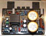
I ordered a few weeks ago 2 amplifiers LM49810-based modules from this website : www.chip-pcb.cn
The problem is that I'm experiencing problems adjusting bias. According to the documentation, I should adjust the potentiometer in order to read 22mV across "Re". Unfortunately, I read 0mV whatever position the potentiometer is.
When I powered up the amplifier module, everything went fine. (No explosion, red-hot resistor or magic smoke). The LM49810 becomes very slightly warm after a few minutes which seems perfectly normal)
Being a complete ignorant concerning amplifier debugging, I suspect the module to be stucked in "Mute" mode but I have absolutely no idea how to confirm this. Datasheet mention the LM49810 needs 50ìA to 100ìA on Mute pin to swich to "play" mode.
How can I read such a low value ?
I'm reading 0-1mV on module's output which may be due to my multimeter Fluke 111 imprecision.
I'm feeding 44VDC to the modules using conventional non-rectified power supply. Could it be the voltage too low ?
I've attached the schematic
Any help would be greatly appreciated. Thanks !
Hi !
First of all, thank you.
In response to your comment, unfortunately there's no pads provided to switch mute on/off. As you wrote, it should be constatly on.
I'm not very familiar with zener diode but is there a way to calculate which voltage should I read on LM49810's pin 2 or on the mute circuitry (Rw, Cw, Dw, Rm)
Thank you for your help !
Hello !
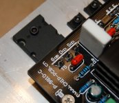
Here's a picture how T5 is mounted. By looking at the pcb traces :
T5 pin labeled G(b) is tied to Rz (100ohms)
T5 pin labeled D(c) is tied to CL (0,1uF)
T5 pin labeled S(e) is tied to Re (0,22ohms)
I suppose if T5 would have been installed backward, something would have blown up right ?
Thank you very much for your help guys
Emmanuel
Attachments
Hi,
I have a similar kit from them and I presume they tested it for supply voltages close to 100V. Rw=22k is marginally good at those voltages.
For 44V rail voltage I think Rw should be lower. A 4k7 / 1W should do a proper job to bias the Zener and keep it at 5.1V even when the LED is on. Assuming 4mA through the LED then Rx should be around 820 ohm. The other values seem to be OK. (Rm=33k, Cw=47u, Dw=5V1 type)
Elkaid said:Hi everyone,
I ordered a few weeks ago 2 amplifiers LM49810-based modules from this website : www.chip-pcb.cn
The problem is that I'm experiencing problems adjusting bias. According to the documentation, I should adjust the potentiometer in order to read 22mV across "Re". Unfortunately, I read 0mV whatever position the potentiometer is.
When I powered up the amplifier module, everything went fine. (No explosion, red-hot resistor or magic smoke). The LM49810 becomes very slightly warm after a few minutes which seems perfectly normal)
Being a complete ignorant concerning amplifier debugging, I suspect the module to be stucked in "Mute" mode but I have absolutely no idea how to confirm this. Datasheet mention the LM49810 needs 50ìA to 100ìA on Mute pin to swich to "play" mode.
How can I read such a low value ?
I'm reading 0-1mV on module's output which may be due to my multimeter Fluke 111 imprecision.
I'm feeding 44VDC to the modules using conventional non-rectified power supply. Could it be the voltage too low ?
I've attached the schematic
Any help would be greatly appreciated. Thanks !
I have a pair of the same amp y0u ordered, I think it is NOT a good idea to release to the public the commercial in confidence the circuit diagram that has been given to you. Did you get permission to do so?
The developer took many hours/days to come up with the circuit, intellectual property from the East is the same as from the West.
Diagram release violating copyright
Ttan98, pardon your poor English, but the way I have viewed this thread, there is no issue about violating any IP or copyright in Elkaid's posts. He simply showed a photo of a pcb assembly. Exactly how is that any IP or copyright violation?
Ttan98, pardon your poor English, but the way I have viewed this thread, there is no issue about violating any IP or copyright in Elkaid's posts. He simply showed a photo of a pcb assembly. Exactly how is that any IP or copyright violation?
Re: Re: LM49810 amplifier

 Notice also that intellectual property only exists in a few countries. You can't really protect ideas unless you get a patent or not reveal it at all.
Where is the schematic diagram? So why this post?ttan98 said:
I have a pair of the same amp y0u ordered, I think it is NOT a good idea to release to the public the commercial in confidence the circuit diagram that has been given to you. Did you get permission to do so?
The developer took many hours/days to come up with the circuit, intellectual property from the East is the same as from the West.
Notice also that intellectual property only exists in a few countries. You can't really protect ideas unless you get a patent or not reveal it at all.What do you mean non-rectified? Do you have + voltage as much as expected and a - voltage? 40-50 volts?Elkaid said:I'm feeding 44VDC to the modules using conventional non-rectified power supply. Could it be the voltage too low ?
Re: Re: Re: LM49810 amplifier
Both of you came too late the schematic has been removed. It was shown in the 1st post.
Rw=15k is ok for even at 34VDc supply. I got my amp working. It is playing now.
larzman said:Ttan98, pardon your poor English, but the way I have viewed this thread, there is no issue about violating any IP or copyright in Elkaid's posts. He simply showed a photo of a pcb assembly. Exactly how is that any IP or copyright violation?
peranders said:
Where is the schematic diagram? So why this post?
Both of you came too late the schematic has been removed. It was shown in the 1st post.
Rw=15k is ok for even at 34VDc supply. I got my amp working. It is playing now.
What do you mean non-rectified? Do you have + voltage as much as expected and a - voltage? 40-50 volts?
Sorry, I meant non-regulated. Using 30 Volts transformer + diode rectifier + 40mF, I get around +44 and -44VDC
The amplifier is working (nicely) but I have no idea which value the bias is set at since I'm unable to read voltage across Re (0.22ohm 5W). (I get 0 mV)Good, I'll hope the threadstarter also will get his amp working.
I don't know if bias adjustment difference is supposed to be easily heard but in my case, there's no much difference between the bias adjustment potentiometer being rotated completely clockwise or counter-clockwise. No much effect on mosfet temperature neither.
Tonight I'm going to try reading the value with my 'scope or another multimeter. I'm beginning to suspect a faulty multimeter.
I'll keep you posted
T1 -> 2SC5171 (base: -1.89V collector: 1.06V emitter: 2.45V)
The error is in the bias circuit. I'm pretty sure of it.
The voltage across collector emiiter should be 6-8 volt
Base-emitter = 0.62-0.67 V if you have made things right.
Are you really sure you have mounted this part right? 100% control over B E C? If you interchange C and E you will get a 5 V transistor with Hfe of 5-10. It looks like that.
The voltage across T1 is calculated like this:
0.65*(1+(RB1/(RB2+Rp)))
Take a real close look in the datasheet because the design is more or less a 100% blue print of it.
In theory 44 V rails give you:
(44*44)/(8*2) = 121 watts
In the real life you'll get less because of not being able to drive the mosfets into saturation. I'll guess you'll loose up 10 volts peak.
Hi !
Here's some updates. I checked bias circuit and it looks ok to me. (Well, the components values seems ok and correctly placed)
I measured some values on T1
With Rp fully off I get on T1 :
B: -1.01V
E: -1.57V
C: 1.39V
With Rp fully on I get on T1 :
B: -2.19V
E: -2.72V
C: 1.62V
I still get nothing across Re
I'm completely clueless.... Any suggestions guys ?
Here's some updates. I checked bias circuit and it looks ok to me. (Well, the components values seems ok and correctly placed)
I measured some values on T1
With Rp fully off I get on T1 :
B: -1.01V
E: -1.57V
C: 1.39V
With Rp fully on I get on T1 :
B: -2.19V
E: -2.72V
C: 1.62V
I only get from around 3V to 4.35VThe voltage across collector emiiter should be 6-8 volt
I get 0.57VBase-emitter = 0.62-0.67 V if you have made things right.
I still get nothing across Re
I'm completely clueless.... Any suggestions guys ?
I have the transistor version of your kit, I manage to make to work. T4 & T5 are transistors.
you find turning the pot clockwise will change the voltages of the bases of T2 & T3. voltage of T2 can be increased pass 1.2-1.25V, similarly with T3 pass -1.2-1.26V, With this voltage, T4 and T5 will turn on.
Once you pass the above voltages the current on T4 & T5 will increase QUICKLY. Take care then.
If you CANNOT reach +/- 1.2-1.25V then something maybe wrong.
your version is no much different, you need to increase the gate and drain voltage pass certain point before the T4 & T5 will turn on. That value will depend on that model of mosfet, it varies from model to model. I don't know the value, ask the kit seller.
Hello !
Thanks for the reply
You're right... I can even reach values around +/- 2V. However, I measured a voltage difference between T2 and T3 base of about 200mV.
I don't know if that's an issue (yet)
Thank you for your help !
Thanks for the reply
you find turning the pot clockwise will change the voltages of the bases of T2 & T3. voltage of T2 can be increased pass 1.2-1.25V, similarly with T3 pass -1.2-1.26V, With this voltage, T4 and T5 will turn on.
You're right... I can even reach values around +/- 2V. However, I measured a voltage difference between T2 and T3 base of about 200mV.
I don't know if that's an issue (yet)
Thank you for your help !
- Status
- This old topic is closed. If you want to reopen this topic, contact a moderator using the "Report Post" button.
- Home
- Amplifiers
- Chip Amps
- LM49810 amplifier