A stable amplifier won't cause a rush to purchase an ineffective tone control.+32dB (40times) is quite a high gain. Do you have a reason for going this high?
A rather weak modern source performs better when not run to max.
Other than those two things, I can't imagine why the amp gain is that high.
Mr. Daniel
Please see the picture.
Thank you
Vijay
India
Two cheap 10R 1/4w cost much less than a 5R 1/2w resistor.
This can be replaced with one 1/2w resistor; and, there are many other options (most of which won't be needed if the amp is stable).
Two cheap 220u caps sum to 440u and result in maximum quality.
This cannot be replaced with a single part because it would cost either a higher gain setting resulting in lower resolution, or cut the power voltage (not slightly) to increase stability. I say, make room on the board for duplicate power caps, run tandem. It probably will be worth doing that for all of audio amplifiers.
Edit: Don't go nuts--I said two, not fifty.
Hi Ivo-Cici
Thanks. I'll have a look at it and will try it. I am currently collecting some materials on the inverting 1875. I have built one according to my taste but eager to check other solution. I am using a single 2SK170BL per channel as a buffer and quite happy with the result. The same resistor value as in the database for non-inverting but configured in inverting mode.
I have DCB1 and connect it to my non-inverting LM1875 per datasheet. They do sound a bit different and difficult to tell. Thanks.
Trying a simple LM1875 with 2SK170BL
Hi,
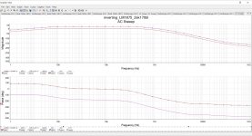
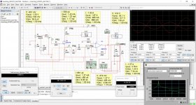
Attached are simulations of a simple LM1875 with a single 2SK170BL (left-overs from a DCB1 Buffer project). Is it stable based on the schematic?
I have built it with resistors and cap values, they are available with me currently. It does not show an excessive temperature raise and it's been two weeks operating. DC out is about 1 mV or so, similar to my non-inverting LM1875.
I have not tried the T-network because as I read it, the T-network is useful if we build without buffer. Please correct me if I am wrong.
PSU is a 18-CT-18 transformer with simple 2x2200 uF per rail.
Any comment on the bode-plot?
Hi,
Attached are simulations of a simple LM1875 with a single 2SK170BL (left-overs from a DCB1 Buffer project). Is it stable based on the schematic?
I have built it with resistors and cap values, they are available with me currently. It does not show an excessive temperature raise and it's been two weeks operating. DC out is about 1 mV or so, similar to my non-inverting LM1875.
I have not tried the T-network because as I read it, the T-network is useful if we build without buffer. Please correct me if I am wrong.
PSU is a 18-CT-18 transformer with simple 2x2200 uF per rail.
Any comment on the bode-plot?
Attachments
hi guys,
any of you tried inverting LM1875 instead of the noninverting?
some said it sounds better in the inverting mode.
any comments and thoughts you could kindly share here?
thanks
ps. hope this question is ok in this thread")
Yes, it does. But it needs input buffer.
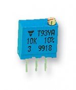
For the multi-turn type you have shown there are two pin outs:Mr. Daniel
There are three pinouts on a 200R trimmer. How do I attach it to the schematic? Eagle has 3 pins for all trimmers.
1 Pin = Input
2 Pin = Ground
3 Pin = Output
Am I right?
Thank you
Vijay
the inline version and the offset version.
The offset version has the wiper (pin2) offset to one side from the two outer pins. This prevents the VR being inserted the wrong way round.
The inline version can be inserted either way around.
Pin1 is connected to one end of the resistive track.
Pin3 is connected to the other end of the track.
Pin2 is connected to the wiper.
There is no "ground" inherent to any of these pins
Last edited:
Would the Rod Elliott design work? It has no 1M ohm resistor in the input stage before the 2.2uF bipolar electrolytic capacitor. Could someone explain to me the importance of the 1M ohm resistor.
Thank you.
This project exactly:
Single Chip 25W Amplifier (Project 72)
Thank you.
This project exactly:
Single Chip 25W Amplifier (Project 72)
Last edited:
Would the Rod Elliott design work? It has no 1M ohm resistor in the input stage before the 2.2uF bipolar electrolytic capacitor. Could someone explain to me the importance of the 1M ohm resistor.
Thank you.
This project exactly:
Single Chip 25W Amplifier (Project 72)
Main reason is to discharge the capacitor while powered off. The value is high enough where it shouldn't effect the circuit, but still provides a path to ground.
Not an issue if a potentiometer is part of your circuit.
Hey people,
I'm the new guy. My name is Jochen, I'm 48 years old an located in Germany. I got plenty of diy experience in building & repairing PC's, but I'm totally new to the audio thing.
I've built my first chipamps a few days ago and I love it. As I have no audio equipment at all besides my headphones and a few soundcards, the plan is to build 2.1 active speakers with the option to 5.1 surround for movies.
I'm always pretty broken and I love to repair or build technical stuff, so I deceided to create my own speakers and not to buy a kit. Dumb as I was, I thought just putting the TSP and some dimensions in a PC program would be enough to have my own speakers calculated and ready to build. Ok, its not as easy as I thought, but its fun, an even without the second, not yet complete, satellite and with just a 6db hi-pass capacitor as crossover, to me it sounds great.
Until now I've got two LM1875 for the satellites and one TDA7293 for the subwoofer. As source and active subwoofer- crossover I'm using a Asus Xonar D2X soundcard wich works really fine.
Right now painting is on the schedule, and this really sucks. Not much room, crappy tools, cheap paint ... but I've got time and its getting better. When the painting is done, I'm gonna build the crossovers.
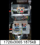
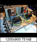
The installation on the pics is just provisionally, but I really like how it sounds. More to come when everything is done.
I'm the new guy. My name is Jochen, I'm 48 years old an located in Germany. I got plenty of diy experience in building & repairing PC's, but I'm totally new to the audio thing.
I've built my first chipamps a few days ago and I love it. As I have no audio equipment at all besides my headphones and a few soundcards, the plan is to build 2.1 active speakers with the option to 5.1 surround for movies.
I'm always pretty broken and I love to repair or build technical stuff, so I deceided to create my own speakers and not to buy a kit. Dumb as I was, I thought just putting the TSP and some dimensions in a PC program would be enough to have my own speakers calculated and ready to build. Ok, its not as easy as I thought, but its fun, an even without the second, not yet complete, satellite and with just a 6db hi-pass capacitor as crossover, to me it sounds great
.Until now I've got two LM1875 for the satellites and one TDA7293 for the subwoofer. As source and active subwoofer- crossover I'm using a Asus Xonar D2X soundcard wich works really fine.
Right now painting is on the schedule, and this really sucks. Not much room, crappy tools, cheap paint ... but I've got time and its getting better. When the painting is done, I'm gonna build the crossovers.
The installation on the pics is just provisionally, but I really like how it sounds. More to come when everything is done.


Clue,
please attach your pictures.
How to attach images to your posts.
the 1200x900 is probably OK when attached.
The 1726x3065 is going to be too big for most of our screens/monitors.
Crop and compress/resize before you attach.
please attach your pictures.
How to attach images to your posts.
the 1200x900 is probably OK when attached.
The 1726x3065 is going to be too big for most of our screens/monitors.
Crop and compress/resize before you attach.
Last edited:
Can I use it for small subwoofer?
Depends on the subwoofer driver wattage rating ... but it is not recommended as if the LM1875 was overdriven into clipping it sounds nasty ... based on my past experience
Hi Daniel
I’m in the process of building the amp according to your fine instructions.
As I understand there are 2 choices of schematics. The “original” one shown in post #1 and the Turbo II. Is that correct?
What are the differencies in sound between the 2 layouts?
In short: Which one should I build if best sound quality is wanted?
Regards Kurt
Hi folks
1. What is the purpose of the 1R 3w resistors in the power supply from post #1?
2. Which components "need" to be of good quality and which doesn't in order to make the amp sound its best?
3. What specs do you recommend for these better quality components (resistors, capacitors)?
Regards
Kurt
1. What is the purpose of the 1R 3w resistors in the power supply from post #1?
2. Which components "need" to be of good quality and which doesn't in order to make the amp sound its best?
3. What specs do you recommend for these better quality components (resistors, capacitors)?
Regards
Kurt
As no one has spoken I'll give my thoughts:
The 1 ohm resistors increase the impedance of the supply as seen by the transformer and so help reduce the overall 100/120Hz ripple more effectively than if they were not present.
The downside is that they reduce the 'stiffness' of the supply meaning that the regulation becomes poorer i.e. the rails will sag more under sustained load. Its the designers choice to do it this way.
All parts should be of good commercial quality and (imo) exotic or boutique parts are not required.
The electrolytic caps should be a reputable brand and of 105C temperature rating. Resistors (unless specified otherwise) should be metal film types of 0.5 or 0.6 watt and 2% or 1% tolerance. The 1 ohms you asked about would typically be a small wirewound vitreous enamel type.
The 2.2uF input cap should be a film type.
I'll give my thoughts:The 1 ohm resistors increase the impedance of the supply as seen by the transformer and so help reduce the overall 100/120Hz ripple more effectively than if they were not present.
The downside is that they reduce the 'stiffness' of the supply meaning that the regulation becomes poorer i.e. the rails will sag more under sustained load. Its the designers choice to do it this way.
All parts should be of good commercial quality and (imo) exotic or boutique parts are not required.
The electrolytic caps should be a reputable brand and of 105C temperature rating. Resistors (unless specified otherwise) should be metal film types of 0.5 or 0.6 watt and 2% or 1% tolerance. The 1 ohms you asked about would typically be a small wirewound vitreous enamel type.
The 2.2uF input cap should be a film type.
- Home
- Amplifiers
- Chip Amps
- Beginner's Gainclone, HiFi LM1875, The Amplifier Board