Cherry LF Com NFB and LM1875, possible?
Hi AndrewT and all other members,
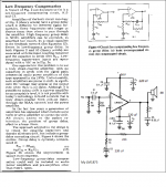
Here is the schematic for my LM1875 as well as extracted materials from Dr. Cherry's publication on LF comp.
Please help on finding the "correct" value.") Has anyone done a simulation on this LM1875 with Cherry's LF comp?
Has anyone done a simulation on this LM1875 with Cherry's LF comp?
Thanks in advance.
Hi AndrewT and all other members,
Here is the schematic for my LM1875 as well as extracted materials from Dr. Cherry's publication on LF comp.
Please help on finding the "correct" value.
Has anyone done a simulation on this LM1875 with Cherry's LF comp?Thanks in advance.
Attachments
starting with R3=1k and C2=220uF.
Gain is 23times.
The added resistor is 44k (use two 22k in series) = RF3
The added capacitor CF2 = R3*C2/RF2 = 1k*220uF/22k = 10uF
Change R2 from 22k to 66k (use 68k and add a 1M or 2M parallel trimmer to set the output offset to zero mVdc, then replace trimmer with the nearest value fixed resistor).
C1 = C2 *R3 / R2new / sqrt(2) = 220uF*1k/66k/1.4 <= 2u38F (use 2u2F)
Your LF bandwidth has increased from 3.3Hz to 1.1Hz
You could reduce all the capacitors by a factor of 2.2 to
C1 = 1uF, C2 = 100uF & CF2 = 4u5F, for F-3dB=2.4Hz
or reduce by a factor of 3 to
C1 = 0u68F, C2 = 72u6F, CF2 = 3u3F, for F-3dB=3.5Hz
In these latter two cases you are allowed to use capacitors substantially smaller than the original and still have adequate LF bandwidth.
BTW,
I have a discrete Power Amplifier with R1=2M2, R2=66k, R3=1k, NFBupper=RF2=22k, RF3= 44k, (two smd 805 in series in the copper trace), C1=1uF, C2=CF1=120uF (measures 120u8F), CF2=5u5F (two 10uF electro in series)
Last edited:
Certainly. We don't know whether your source will perform better with a lighter or heavier load. So, you'll need to try, to find out.Hi Daniel, I have read the post but could not find the reason why you changed 22k to 15k. Could you elaborate more on this?
If your feedback resistor is 22k and feedback-shunt resistor is 1k, then it is possible to use a range of input load from 4.4k to 21k.
Many blame different amplifiers for no bass, or spitty treble, or muddled midrange, or any number of excuses for not liking the "PERFORMANCE" of the amplifier.
It is usually NOT the amplifier that is at fault. It is the BUILDER'S IMPLEMENTATION.
Build the amplifier correctly, test it thoroughly to ensure you have built it correctly, then listen to the amplifier PERFORMING correctly.
It is usually NOT the amplifier that is at fault. It is the BUILDER'S IMPLEMENTATION.
Build the amplifier correctly, test it thoroughly to ensure you have built it correctly, then listen to the amplifier PERFORMING correctly.
I totally agree with post 506. I have learned quite a lot recently through discussions in this forum. I can also see the mistakes I made previously and how each of the components affect the overall system performance. Especially for an amp that I have left about a year since my first built of this LM1875.
Additional report, I have just implemented a log-law faking resistor, a parallel of 1k2 resistor to the 10k pot. It causes my amp a bit warmer than without it. Do you think these log-law faking resistors have something to do with this temperature increase? (Uh, still asking question... Didn't I say I have learned?)
An one more thing, as this amp improves, so do my ears... :-D The russian caps I use as the input cap really works well.
Many many thanks.
The 1k2 both loads the Source and loads the Receiver.
I can't see why the extra loading, on the Receiver input, leads to an increase in temperature.
Unless somehow that resistor which is connected to +IN, very indirectly, causes the Receiver to oscillate. Surely that symptom would be obvious.
I can't see why the extra loading, on the Receiver input, leads to an increase in temperature.
Unless somehow that resistor which is connected to +IN, very indirectly, causes the Receiver to oscillate. Surely that symptom would be obvious.
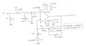
LM1875 + Dr. Cherry's LF Compensation
As promised, this is the schematic. Please help checking the component value especially the polarity of capacitor (C7) in the LF compensation feedback. It is a 10uF and I guess it should be of electrolytic type.
As the total feedback resistor is now 66k, isn't the gain of my amplifier now 67 times?
I assume that the input impedance Rin should be equal to total gain feedback capacitor. 22k Rf and 22k Rin, now 66k Rf and 66k Rin, and if one manages to equalize them (Rf = Rin) then zero mV of dc at te output. Is it correct?
BTW, I have removed the 1k2 resistor from the vol pot, the temperature is lower than with the resistor installed, actually I soldered them right at the pot's legs.
Another thought, I think an amplifier board should have a ground bus, I noticed Dr. Cherry established a bold straight line for ground bus in the middle of his NDFL PCB as in ETI May 1983. With similar ground bus, created by connecting the pixels of veroboard using soldering tin, my LM1875 does not make thump sound when turned off. Heatsink is cool even without 100nF bypass cap (I just experimented by removing them to observe what happens). So, thinking that unusual heat is a symptom of oscillation, I think it's not oscillating, right?
Thanks
Attachments
Last edited:
the 44k is in parallel to the 10uF.
The feedback is dependent on 1+{upper impedance / lower impedance}
At VLF the 10uF has an impedance and affects the gain.
But using the formula given by Cherry, the impedance of the 10uF is much smaller than the 44k through the whole audio passband range.
It's the same for the lower capacitor. It too has a VLF impedance, but in the audio passband range it's impedance is much less than the 1k.
Measure the DC across the electros. They will be in the mV range. You can then orient them in the correct polarity.
But I used back to back electros that I reformed to the full 50Vdc before installing.
They will hold a very low leakage for a long time and are tolerant of a small DC offset as well.
Last edited:
Thanks.
I forgot that cap impedance varies with frequency. So, assuming 1 kHz, then the upper capacitor's reactance is 1/(2*pi*1k*10u), i.e. ~16R which is in parallel with a 44k still yields approximately ~16R which is in series with a 22k and the total upper impedance is ~22k.
The same rule applies to lower impedance, lower cap reactance is 1/(2*pi*1k*220u), i.e. ~0.7R which is very small value. Hence the lower impedance is about 1k. Interestingly, because the impedance at low frequency, say 20 Hz, is approaching 1k, then it will affect the gain at lower frequency and leave out the higher frequency. Very clever.
So for 1 kHz and above, the gain setting is about the same as the original circuit. I am planning to use a bipolar/non-polar electrolytic, I think it's easier.
Last edited:
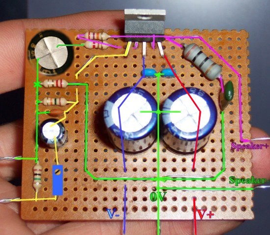
This is for the purpose of an accessible hifi chip amplifier, it is in reference to Commercial complete Gainclone kit for a beginner? - diyAudio and it is by request. Here's LM1875, at low cost, and easily made by following the "play by play" photographic format (starting at post#24). The LM1875's "only 5 pins hookup," and the absence of spike system noise, can give you 25 watts per channel of high fidelity, at a bargain price, and with an easy time of building your own amplifier.
But, first, let's have a look at how "not" to use the LM1875: If you're planning the maneuver of pushing inefficient speakers with great force, then try something else. Our introductory LM1875 project here, has not been paralleled to withstand 4 ohm speakers.
LM1875 works great with efficient 8 ohm or 16 ohm speakers: Since this thread starts from Gychang's post and since he is famous for the full range hifi genre speakers, then I think that the laid-back hifi sounds of LM1875 could be a perfect fit. Any reasonably efficient 8 ohm speaker is suitable.
Circa 2012 update
Suitable transformer voltage is actually 18+18vac or less. These transformers are affordable: Antek - AN-0518 Monobloc/dualmono build is recommended for current control and wider imaging. For good longevity don't give an LM1875 chip access to more than 1a~1.5a worth of transformer. That's why Monoblocs really make sense.
Input load resistor should actually be 10k (not 15k).
Due to lack of NFB-shunt cap, consider adding high quality output cap assembly, in series to the speaker, for long lasting speaker protection. Adjust capacitance value to suit speaker size for enhanced headroom. Output caps strongly recommended if using irreplaceable speakers with Any chip amplifier kit or project. (click this link to see older nearfield design). The 2012 edition is a slightly refined version of the circa 2008 original, and suited to studio mixer/desktop use.
Circa 2013 update
With its gain of 34X, a computer sound card or digiplayer can drive this amplifier easily, without straining the source device. Now for 2013, it does have the NFB-shunt cap so it can't amplify DC. The parts paralleling shown is for high end quality at low cost. Output caps are no longer shown on the schematic but they are fun to use for bass and headroom enhancement. Tone option: To compensate for a peakish speaker, add just ONE of this model 4.7u from V+ to V- (rail2rail cap) at the amplifier board's power circuit to cause quieter midrange with higher resolution. Mains fuse and speaker jack fuse are suggested. Each monobloc produces up to 25 watts of power to an 8 ohm speaker.
Power Supply
Here are CRC power supplies for these monoblocs:
Option: You can use 3300uF 35v or 50v caps, such as Nichicon FW or Panasonic FC.
Transformer Voltage
Example transformer voltage is 18+18vac
Click on best match for your application to see a hookup diagram.
♦ Your mains is 120vac and your transformer is 18+18 or less?
♦ Your mains is 230vac and your transformer is 18+18 or less?
♦ Your mains is 120vac and your transformer is 36+36 or less?(dual primaries in series)
♦ Your mains is 230vac and your transformer is 9+9 or less?(dual primaries in parallel)
(please assure that the transformer output is 18+18vac or less)
And see Decibel Dungeon for a briefing on how to power your audio amplifier, including construction and safety.
Transformer Amperage
Greater durability can be had via good design and a right-sized transformer, or you could use a lot of fuses.
Monobloc/Dualmono:
♦ 36va*0.67=24 watts, which is perfect; however, we might want to adapt to dual secondaries and twin bridge rectifiers to maximize the little 1 ampere transformer. Use a mains fuse.
♦ 50va*0.67=33 watts, which is a bit too much; however, that's safe if given a Center Tap transformer (just one bridge rectifier) And the CRC power supply. Use a mains fuse and speaker jack fuse.
Stereo:
♦ 100va, instead of breaking chips, you may choose to use mains fuse and rails fuses for right channel amplifier board and rails fuses for left channel amplifier board and speaker jack fuses for each speaker. No matter if stereo or monobloc, a minimum of 7 fuses is mandatory if the transformer is greater than 50va.
Before powering on the new amp
Here's AndrewT's checklist:
I would also like to suggest putting a capacitor in series with the speaker for protector. It costs less than replacement speakers. And you get the Bonus of fun bass efficiency tuning for maximized headroom (a lot more power), by simply reducing the capacitance size to match what the speaker can do and roll-off what it can't do. This makes your amplifier output only what the speaker can use. Cheaper: If installed at speaker ground of a stereo build, two speakers can share the protector.
Avoiding destruction
It may be very difficult to get up and running without the NFB-Shunt Cap, so here's a photo of the old 2008 project re-fitted for greater durability and so it won't amplify DC. This added part, NFB-Shunt Cap is the electrolytic cap in the upper-left corner pictured. Whatever else it may do, it is absolutely certain to give you better odds at building a working amplifier. So, use it.
Hi,
can someone please explain the purpose of the diode on the 25V power rail. Thanks.
Do you mean the top schematic?
There are two diodes, one in each supply rail.
these will protect against reverse/wrong connections of the dual supply rails.
I prefer to install the protection diodes (1n4002) across the first set of capacitors on the PCB. These don't lose any voltage. They also pull current through a wrongly connected PSU and turn on the Mains Bulb Tester. WARNING !!!! something is wrong !!!!!
Then check voltages and you will find the amp and the capacitors are limited to less than 1V of reverse voltage, equals no damage.
The diodes have a second function. They act like a veritable resistor between the PSU and amp. High resistance for low current demand and a low resistance for a high current demand.
I have been experimenting with a parallel diode and resistor combination that works very well too.
I have been experimenting with a parallel diode and resistor combination that works very well too.
Hi Daniel,
I just create single layer pcb layout based on your LM1875 Turbo II with little modification.
for C NFB, I prepare to use bigger value, so I add C9 --> C8 || C9
for R NFB / Gain, I use R5 20K with R6 1K.
and I remove the diode in V+ and V-
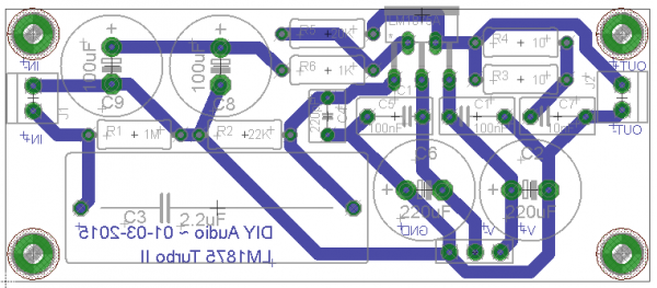
I need some opinion, suggestion on this layout before I make the pcb
I just create single layer pcb layout based on your LM1875 Turbo II with little modification.
for C NFB, I prepare to use bigger value, so I add C9 --> C8 || C9
for R NFB / Gain, I use R5 20K with R6 1K.
and I remove the diode in V+ and V-
I need some opinion, suggestion on this layout before I make the pcb
Last edited:
That's not a Turbo II at all.
Most problematically, the lower gain shown (of the datasheet schema) can cause the need of lower voltage (not more than 17+17vdc rails) and you'll need all FOUR output filter pieces mentioned in the datasheet, the output RC (from the datasheet schema) and the L||R (in the stability chapter). So, because of copying the datasheet schematic, you'll find your output RC values also in the datasheet, but what they didn't mention is that the cap for it is a polyester dip or mylar dip cap (green or red blob), not a box cap.
C9 and C8 are clever that way; however, the odd "V" shaped space in the ground track between the caps, needs filled up solid. Also, the 100u value is too small (because datasheet schema's 1k) so use, conveniently, 220u (or preferably 270u) for all of the big electrolytic caps.
The 100n caps are shown a box shape; however, it is more likely that you'd want a Ceramic X7R or even inexpensive ceramic disc could work better than a poly at that location.
Also, you need a separate track for the speaker return.
Last edited:
The Turbo II did need an update to show a "groundlift" resistor, which doesn't do much for or to audio but REALLY helps with layout.
2.2R groundlift is shown. The value is plenty big enough to help with layout. However, if a larger value is used, such as 10R~390R, parallel the groundlift resistor with a little cap to prevent treble droop.
2.2R groundlift is shown. The value is plenty big enough to help with layout.
However, if a larger value is used, such as 10R~390R, parallel the groundlift resistor with a little cap to prevent treble droop.Attachments
I want to build this as my first speaker amp. I am a little confused because there are many variations and different options for parts. Which one is most up to date, best design?
http://www.diyaudio.com/forums/atta...875-amplifier-board-lm1875_turbo-ii_color.gif
or
http://www.diyaudio.com/forums/atta...875-amplifier-board-lm1875_daniel_2013-ii.gif
or another one?
What are the exact ratings for perfect transformer? There is a place that makes custom toroids for stock prices. So tell me 19.7V or any ood rating, it will be custom after all, lets exploit it.
Dual rail or two seperate? Would dual mono be more expensive than dual rail?
I thought i could save some money with other type of transformer but a little search revealed that they about the same price as toroidals.
I couldn't find good brand caps locally, just generic stuff. Is it important?
I will probably come up with more questions as i progress. Please treat this newb well
http://www.diyaudio.com/forums/atta...875-amplifier-board-lm1875_turbo-ii_color.gif
or
http://www.diyaudio.com/forums/atta...875-amplifier-board-lm1875_daniel_2013-ii.gif
or another one?
What are the exact ratings for perfect transformer? There is a place that makes custom toroids for stock prices. So tell me 19.7V or any ood rating, it will be custom after all, lets exploit it
.Dual rail or two seperate? Would dual mono be more expensive than dual rail?
I thought i could save some money with other type of transformer but a little search revealed that they about the same price as toroidals.
I couldn't find good brand caps locally, just generic stuff. Is it important?
I will probably come up with more questions as i progress. Please treat this newb well
- Home
- Amplifiers
- Chip Amps
- Beginner's Gainclone, HiFi LM1875, The Amplifier Board