![28022HQ[1].JPG](/community/data/attachments/392/392047-2593082847019abb07da2b34c0e0eeb3.jpg)
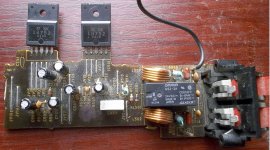
 Ok I have had a quick look .. disregard the psu side of things at the moment .. I have adjusted the values on daniels scema relating to the input and feed back section. I did recheck a couple of times as the values seem a little odd I even used my DVM to check aswell.. as for decoupling 1u electrolytics have been used and not very close to the ic at all and for smoothing 3300u
Last edited:
I am not familiar with the 1875 datasheet.
Is the 5R+10nF the recommended output Zobel?
Have you mounted the Output Zobel at the output Pin and taken it to the nearest Power Ground?
The Input RF filter has an undefined source impedance. Cable inductance and source Rs.
I suggest you add a fixed resistor to define the attenuation. Try 200r to 2k0.
The NFB DC blocker is set too low, 52ms.
The input Filter DC blocker is set to 48ms. These are too close. Try 100uF instead of 47uF.
Install the ceramic part of Cs at the power Pins.
I am not familiar with the 1875 datasheet.
Is the 5R+10nF the recommended output Zobel?
Have you mounted the Output Zobel at the output Pin and taken it to the nearest Power Ground?
The Input RF filter has an undefined source impedance. Cable inductance and source Rs.
I suggest you add a fixed resistor to define the attenuation. Try 200r to 2k0.
The NFB DC blocker is set too low, 52ms.
The input Filter DC blocker is set to 48ms. These are too close. Try 100uF instead of 47uF.
Install the ceramic part of Cs at the power Pins.


That is Sanken SI18752, which works fine with the assembly method at post#24 through post#45 of this thread (making amplifier boards for LM1875, LM675, TDA2030, TDA2030A, TDA2040, TDA2050, SI18751, SI18752, and other pin compatibles).
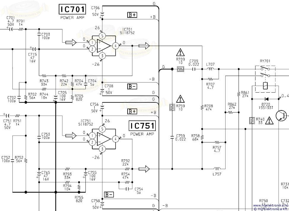
Meanwhile, Post#421 shows the compensation used by sony. Well, actually I don't know if that is compensation or tone control (either uses the same parts). Could you have a look at it?
Meanwhile, Post#421 shows the compensation used by sony. Well, actually I don't know if that is compensation or tone control (either uses the same parts). Could you have a look at it?
That is not a National LM1875.
What are you wasting our time for?
Andrew I never asked you for your time .. I also thanked you and Daniel for the informative replies... I never said it was a national lm1875 So why are you wasting your time answering me. if you have a problem just don't reply you do have a choice you know..
Concerned Regards Mark
Hi Daniel. Im going to do a point to point build with these IC,s . . I have had a look at the Sony schematic . Hoping I don't have to use that as will make a point to point build a little involved . I very much hope I have not wasted your time . I did realise the pin out was the same as the lm1875 that is why I posted here another reason is you seem to have fun with IC,s like this and I want some of that fun too. As you can see from the picky of the pcb there are no ceramic or foil capacitors used close to the IC for decoupling purpose . Maybe a silly question Do you think there could be bypass capacitors built into the IC as the layout certainly looks like it would need some
Kind Regards Mark
Kind Regards Mark
Last edited:
post423 shows lm1875Andrew I never asked you for your time .. I also thanked you and Daniel for the informative replies... I never said it was a national lm1875 So why are you wasting your time answering me. if you have a problem just don't reply you do have a choice you know..
Concerned Regards Mark
You are wasting everyone's time that has to read your misinformation.
Im sorry Andrew .. You failed to read all posts before replying.. Now I would like to know when did Everyone vote you in to speak for them .. could a moderator please remove post 423 as to clear up any possibility of someone being miss informed. then could you please check all Andrew t.s posts for all the misinformation posted by him in the past years as you will find plenty..... Andrew T YOU ARE NOT A MODERATOR
Lets please argue about audio electronics instead.
In my opinion, it would be safer to start up with high gain, and then trim it back down as stability permits.
P.S.
I've got a curiosity. Mark, could you check that Denon amp and see if, by chance, it might be an inverting amp? For example: Building a basic inverted Gainclone chip amp using hard-wiring is an inverting amp.
Ah, for non-inverting, I think you'd like some odd ~42x gain (in that ballpark) for a safe start. You can trim it back later, as stability permits, but I do suggest for the first start that the amp run in a very placid stable condition.
*If SI18752 works as Denon assumes, it should be a non-inverting amp
However, for inverting, you could just follow that decibel dungeon LM3875 example (except for pinout) and it will probably start up safely (most chip amplifiers tolerate lower gain when used in inverting mode).
*If SI18752 works as Sony assumes, it should be an inverting amp
To choose between these two:
Does the amplifier require excessively high gain to achieve stability or produce an annoying tonal coloration in non-inverting form? If so, make an inverting amp.
If not, then non-inverting amplifiers are usually easier, because. . .
Caveat of an inverting amp is that you need a near constant input impedance (not a good spot for a volume pot). For this, see the NE5534 at Decibel Dungeon, and if you build that, try to use a Philips, Signetics or Raytheon chip, which are authentic (but if you use Texas Instruments NE5534, don't bias the output to class A--an easier build indeed but not the intended design).
Last edited:
Mark,
When dealing with engineers, please understand that any negative response could not have been about your person and that is because you did not provide that data. So, it, absolutely must, have been all about the data you did provide. The input can be quite beneficial after you interpret it. Don't take it personally! Do please bear in mind that if you want a constructive negative response from an engineer, then you will have to ask for that specifically. And, also remember that if you get any sort of response, that is because he cares.
Yes, that does involve a pause, and some reading between the lines.
I do have many friends who are engineers, and yes, they all seem to share these traits in common. Except just three engineers, and those guys, I assume, may have gotten their cussing expediently completed before responding.
Remember, thing skills and people skills are polar opposites. So, you'll have to decide between perfecting a fantastic circuit or getting coddled, because it is very unlikely to get both. You know, that combination (have your cake and eat it too) is not impossible, but one should not expect it.
Meanwhile, back to engineering. . .
The only time a circuit works perfectly is when it must, so if you want perfect audio, that will only come from a circuit incapable of doing anything else.
Last edited:
Hello!
I have a transformer with 2x21VAC @ 1.8A secondaries IIRC. It is dual secondaries with no centertap. Could I use this transformer to make this project? I'm thinking of also regulating the voltage down to 25VDC since after rectification the transformer should supply roughly 28VDC with smoothing caps added.
I have a transformer with 2x21VAC @ 1.8A secondaries IIRC. It is dual secondaries with no centertap. Could I use this transformer to make this project? I'm thinking of also regulating the voltage down to 25VDC since after rectification the transformer should supply roughly 28VDC with smoothing caps added.
Last edited:
Hi daniel,
I might have to regulate it down even more to handle such phenomena. As it stands now I have sampled a few LT1085/1084.
My main question however was if the transformer I had would be capable of powering two LM1875s in the configuration described in this thread. If I'm not mistaken 2x21VAC @ 1.8A each makes it a 75.6 VA transformer. Looking at the first post this should be OK, maybe pushing it a little, which is why I'm asking for a second opinion.")
The whole setup would be driving 8 ohm speakers.
I might have to regulate it down even more to handle such phenomena. As it stands now I have sampled a few LT1085/1084.
My main question however was if the transformer I had would be capable of powering two LM1875s in the configuration described in this thread. If I'm not mistaken 2x21VAC @ 1.8A each makes it a 75.6 VA transformer. Looking at the first post this should be OK, maybe pushing it a little, which is why I'm asking for a second opinion.
The whole setup would be driving 8 ohm speakers.
- Home
- Amplifiers
- Chip Amps
- Beginner's Gainclone, HiFi LM1875, The Amplifier Board