I made a dual LM1875 PCB with onboard heatsink and powersupply.
I think this would be very nice as first time project")
Good work!
Yes that's the point. It is your opportunity to put a little cap (range 10u~470u) in the power circuit for better clarity, and probably without causing loud mids.Or will there be an improvement in "sonic performance" if I put the cap?
Peter of AudioSector sometimes puts an extra 10u on only the negative rail for a bit better clarity and tone.
Actually, I have done asymmetric decoupling once--One of my radios, which has a passive auto center power circuit, does have an extra little cap on one of its rails, and that worked fine.
EDIT: This post is not general purpose here--it is regarding one sample.
Different power circuits for different chips.
STK and most TDA amplifier board power caps in the range of 100u~270u
Panasonic's 150u is close to perfect. Nearby values work.
Overture series of tv-sound amplifiers, LM3875, LM3876, LM3886, LM4780 amplifier board power caps in the range of 1000u~2200u when the chip is used in non-inverting mode.
Panasonic's 1500u is close to perfect. See exact model at AudioSector.
LM1875 and LM675 amplifier board power caps in the range of 150u~470u
This is similar to many discrete amplifiers.
Panasonic's 270u is close to perfect. Nearby values work.
I don't do that with LM1875. . . because it isn't an LM3875. Different chips have different needs.@danielwritesbac I agree with you,pair of 1000uf & 0.1uF from +/- rail to Gnd is highly recommended.
STK and most TDA amplifier board power caps in the range of 100u~270u
Panasonic's 150u is close to perfect. Nearby values work.
Overture series of tv-sound amplifiers, LM3875, LM3876, LM3886, LM4780 amplifier board power caps in the range of 1000u~2200u when the chip is used in non-inverting mode.
Panasonic's 1500u is close to perfect. See exact model at AudioSector.
LM1875 and LM675 amplifier board power caps in the range of 150u~470u
This is similar to many discrete amplifiers.
Panasonic's 270u is close to perfect. Nearby values work.
Thanks Daniel!
I have actually followed the suggestion to remove the series output cap. Surprisingly, it sounds better! Now I understand that the series output cap was only needed for my other LM1875 which suffers mids distortion as you suggested (the implementation board from XY Hifi).
For my latest version of LM1875, the output cap is not needed to improve the sound. @availlyrics insisted and now I got his point! :-D Thanks.
Now I am going to change the circuit a little bit by removing the 1000 uF rail to rail cap, and installing 470uF per rail as (your 2013 version employs parallel 220uF). I hope it will help the clarity. I also need to limit the amount of components since I am going to do it point-to-point.
@danielwritesbac, do you have any tutorial on doing p2p for LM1875 as you did for TDA7294?
I also might reduce the gain... it's currently using 22k NFB, and 820R of NFB-Resistor. I probably use 22k and 1k.
BTW, has anyone done a microcap simulation for LM1875? I am interested in the .CIR file. Thank you.
Cheers!
--
luq
Yes that's the point. It is your opportunity to put a little cap (range 10u~470u) in the power circuit for better clarity, and probably without causing loud mids.
EDIT: This post is not general purpose here--it is regarding one sample.
Actually I don't, so howabout the fun puzzle of an STK465 point to point instead?@danielwritesbac, do you have any tutorial on doing p2p for LM1875 as you did for TDA7294?
With so many pins that the soldering will be more fun than LM1875's simple 5 pins.
Last edited:
I think I'll skip to TDA7294. I don't have this STK465 and I want to resurrect my old TDA7294 which to my ears sound - subjectively - better than LM1875. I have a pair of them and your post on P2P TDA7294 is challenging.
Still the same question, anyone done simulation on LM1875 using microcap or alike software?
Still the same question, anyone done simulation on LM1875 using microcap or alike software?
Actually I don't, so howabout the fun puzzle of an STK465 point to point instead?
If you are looking for a spice model for the LM1875 chip itself, one did not exist for a long time but I believe that TI.com might now have one. However, if they do, I don't know how good it is, or if it works well (or at all) with anything other than the TINA simulator software. Do a search for "LM1875 spice model" and you should find the posts. You could also just search for a simulation model at ti.com.
Thanks Daniel!
I have actually followed the suggestion to remove the series output cap. Surprisingly, it sounds better! Now I understand that the series output cap was only needed for my other LM1875 which suffers mids distortion as you suggested (the implementation board from XY Hifi)....
I've purchased LM1875 locally from different shops, one LM1875(may be fake?) had problems with mids- I could hear audible distortion from my midrange spk. After swapping it with other LM1875 the problem was solved. My primary suspicion - problems with passives, gnd layout was isolated in this way. May be you can try swapping LM1875.
For my latest version of LM1875, the output cap is not needed to improve the sound. @availlyrics insisted and now I got his point! :-D Thanks
You are most welcome!
BTW if you are going to use direct coupled design, build some sort of basic spk protection circuits like those based on UPC1237.
Last edited:
Tone = Linearity
To get a really great tone from the LM1875, you'd want to make a parallel amplifier. Paralleling increases the output linearity. When you begin with better linearity, you don't have to fight tone later.
The LM1875 resolves better but the old-production TDA7294 (and new-production TDA7293)'s tone is more palatable than LM1875.my old TDA7294 which to my ears sound - subjectively - better than LM1875
To get a really great tone from the LM1875, you'd want to make a parallel amplifier. Paralleling increases the output linearity. When you begin with better linearity, you don't have to fight tone later.
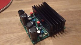
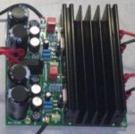
I have almost finished my version of the stereo LM1875 amplifier with onboard powersupply and cooling. I still need some M2.5 bolts for mounting the LM1875s. In the PCB design there are holes under the heatsink for improved heat dissipation.
Attachments
Last edited:
Looks like you are about to bolt the chipamp to the side fin of the heatsink.
The heatsink is designed to reach thermal specification when the device is bolted to the backplate and uses the whole backplate as the interface.
Each time you reduce this the chip will run hotter.
The heatsink is designed to reach thermal specification when the device is bolted to the backplate and uses the whole backplate as the interface.
Each time you reduce this the chip will run hotter.
Looks like you are about to bolt the chipamp to the side fin of the heatsink.
The heatsink is designed to reach thermal specification when the device is bolted to the backplate and uses the whole backplate as the interface.
Each time you reduce this the chip will run hotter.
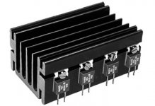
I use this heatsink and they connect the transistors also on the side.According to the website this heatsink is designed for PCB mounting.
http://www.fischerelektronik.de/web_fischer/en_GB/heatsinks/A04/Extruded%20heatsinks%20for%20PCB%20mounting/PR/SK68_/$productCard/dimensionParameters/index.xhtml
Attachments
Last edited:
Yeah, that heatsink is not quite big enough for 2 LM1875's at full blast.
However, my idea of full blast is very scary.
It might handle 2 LM1875's with normal use.
But, I've never tried that.
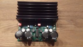
I demonstrated the amplifier on a DIY audio day here in the Netherlands for several hours at pretty high volume and it never ran warm (15-0-15V transformer / 8 ohm speakers)
People were really impressed by the sound quality of this small amplifier, especially when taking into account the total cost (25 euro for PCB / heatsink / components)
Attachments
Last edited:
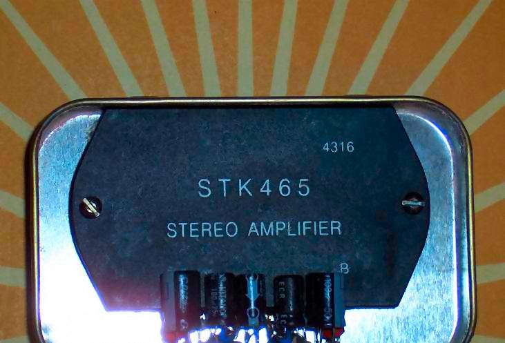
SK 18752 Top3 case = lm1875 ????
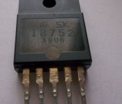
HI .. I like this thread .. I don't have any lm1875. I do have SK 18752 Rescued from a sony A/V surround amplifier . I have searched the web and from what little I found the pinout of this device is the same as lm 1875 . Is this IC A lm1875 in a top3 case.
Best Regards Mark
HI .. I like this thread .. I don't have any lm1875. I do have SK 18752 Rescued from a sony A/V surround amplifier . I have searched the web and from what little I found the pinout of this device is the same as lm 1875 . Is this IC A lm1875 in a top3 case.
Best Regards Mark
Attachments
Last edited:
According to Sony and Denon repair manual schematics, Sanken SI18752 is pin compatible, a little faster and a little stronger, so it is probably not an LM1875. You may need either really high gain or extra work stabilizing. This high gain schematic may work with the SI18752 if you increase the 100k to 115k. Anyway, this one is fairly close.
Edit: Also change that 10n to 22n.
Edit2: Kitchen table stability fine tuning (for when there's no scope): If the sound is all shouty and midrange peakish, increase the gain (change that 100k to a higher figure, a step at a time), or if the sound is all dull/flat with very poor imaging as if sandy/grit, change that 100k to a somewhat lower figure (but not lower than 68k).
The optimal setting could vary depending on many factors, but mostly layout and power voltage (so at a different voltage, the ideal gain may be a different figure).
Last edited:
the double wave logo is not National Semi.HI .. I like this thread .. I don't have any lm1875. I do have SK 18752 Rescued from a sony A/V surround amplifier . I have searched the web and from what little I found the pinout of this device is the same as lm 1875 . Is this IC A lm1875 in a top3 case. ......
The coding is not lm1875.
Both the SK18752 and the lm1875 are 5pin devices.
That does not make them the same !
- Home
- Amplifiers
- Chip Amps
- Beginner's Gainclone, HiFi LM1875, The Amplifier Board