C5 .1uf I'm using a film cap
C6,7 & 8 22uf
The 1 ohm resistor I am using a 1 watt resistor, all the others 1/4 watt
I'm also thinking about upping the big caps to 6800uf or make a separate power supply board.
Amplifier PCB for TDA2030/LM1875 - oddWires
C6,7 & 8 22uf
The 1 ohm resistor I am using a 1 watt resistor, all the others 1/4 watt
I'm also thinking about upping the big caps to 6800uf or make a separate power supply board.
Amplifier PCB for TDA2030/LM1875 - oddWires
You could try C6, 7, 8, 11, 12, 13 all at 100u or 220u.
That will give a different tone.
Also, whichever, maybe C6, C11, is the NFB-shunt cap, you can try the little green 10n (0.01uF) cap from the radio shack added to it for treble helper (and most nearby values work).
Mouser.com has some nice 35v Panasonic FC to try out.
http://www.mouser.com/Passive-Compo...Z1yzh22oZ1yzh20u&Keyword=Panasonic+FC&FS=True
All over this thread are some different optional resistor values that you could try out and they'll all give a somewhat different tone than the generic values in the datasheet. Interestingly, the LM1875 is able to imitate the signature of many, or possibly most, other audio amplifiers. And, there's a lot of that sort of exploration in this thread too.
I do have a tip on bridging: Power the bridged LM1875 amplifier and power supply using a 12+12vac (or less!) transformer.Any tips on bridging or paralleling these boards would be helpful. They seem to be set up for that.
Unfortunately bridging is like amplifiers in series which cuts the quality in half, decreases output device linearity, decreases quality and hinders durability (basically the opposite of paralleling).
Optionally:
Look for the bridged schematic that adds some big output devices, since this solves the output device linearity problem.
Paralleling is actually a lot easier without a board in the way. See the photograph in my signature line. Caps can vary by about 20%, so share all of the caps so as to avoid differences. But don't share any of the resistors--Match the resistors identically with your ohmmeter before using them on LM1875 parallel amp. Whatever differences remain between the two chips will get turned into heat in the pair of big white ballast resistors, about 0.3R (a resistor at the output of each chip). Also, some amplifier output device distortion goes into the ballast resistors, not the speakers. Paralleling improves output device linearity, improves durability, improves quality and usually has more bass slam due to the upgrade of handling more current.
Both bridging And paralleling prevent the amplifier from attempting the mistake of sub-zero output impedance, and so both options may have a better tone than a solo chip. That depends on your speaker.
However, before arranging a great many chip amplifiers to create a high power amplifier, we should probably look at alternatives. Specifically this alternative: http://www.diyaudio.com/forums/solid-state/211905-diyab-amp-honey-badger-build-thread.html
2pcs LM1875T LM675 TDA2030 TDA2030A Audio Power Amplifier PCB DIY | eBay
Cool, I have the same boards (different supplier from the US) and this guy explains how to bridge or parallel them. I'm going to go for it.
Cool, I have the same boards (different supplier from the US) and this guy explains how to bridge or parallel them. I'm going to go for it.
Congrats for the working amplifiers! But, I've had some trouble reading your message and we will find out how well I can guess. . .Hi Daniel- Well I finally have both channels working. No power supply yet though. I have been testing with a 9 0 9V transformer center tapped for 18V and 24 after the regulator. Is that ok for 1 channel.
cheers
No power supply??? Well, I assume that your providing some sort of DC from some sort of power supply else not work for audio. SO, I suppose you have 12vdc positive and 12vdc negative in a standard split rail supply. And by description of "no power supply" I suppose that you have minimal size capacitance.
I think you have described this:
Transformer > bridge rectifier > cables > amp board caps.
Is that right?
The amp board caps are the only power caps?
If those assumptions are correct, then I could say this:
Under-volting has resulted in less output power, maybe about 8W.
If when run at much lower voltage, you'll probably want the gain set lower than my examples (decrease only enough to prevent raspy/gritty, but don't decrease enough to cause a baleful tone--setting in-between the two problems cancels both).
The bass impact could be improved if you add some more capacitance to each rail at your bridge rectifier (see post 1 for power supply examples).
If 8 ohm speakers, you'll run out of voltage well before you run out of current, so that a rather modest size 9-0-9vac transformer should be able to run both amplifier channels (as long as the transformer doesn't get really hot).
It is a valid option to make a pretty little flea power amplifier with LM1875 chips. When not stressed, the output device linearity is maximized and so maximum quality (except for output power) is easier with flea power amplifiers.
Well, there was an awful lot of guesswork in this post, so do please double-check.
Hi Daniel- Sorry for my confusing message.
I have a temporary power supply that I've been using for testing. It is made up of a 9V toroidal transformed center tap for 18V to the rectifier giving me a little over 24V to the amp board.
What I meant was that I don't have a proper supply for these amps yet. I am thinking of getting another 9V transformer and wiring it the same way. I have the one rectifier (it's from another older project) and would build another the same. Do you think that would work ok.
That voltage is too low for me.Hi Daniel- Sorry for my confusing message.
I have a temporary power supply that I've been using for testing. It is made up of a 9V toroidal transformed center tap for 18V to the rectifier giving me a little over 24V to the amp board.
What I meant was that I don't have a proper supply for these amps yet. I am thinking of getting another 9V transformer and wiring it the same way. I have the one rectifier (it's from another older project) and would build another the same. Do you think that would work ok.
What kind of speakers do you have that don't need more than 6 watts to 8 ohms (@1%THD)??
Is your mains voltage 120vac? Does your 30+30vac transformer have dual primaries?
If yes then:
OR if that is not possible:
You could use the 9-0-9vac transformers with Bridged LM1875. Approximately 24 watts to 8 ohms, if the transformers are big enough that they don't get too hot.
If yes then:
OR if that is not possible:
You could use the 9-0-9vac transformers with Bridged LM1875. Approximately 24 watts to 8 ohms, if the transformers are big enough that they don't get too hot.
Thanks.A 220/240Vac transformer run at 120Vac will have approximately half the rated VA.
The 35+35Vac 50VA transformer shown in the example will end up being a 17.5+17.5Vac 25VA transformer when run on 120Vac.
I like the 17.5+17.5Vac. However, for monoblocks, I would prefer 36va if dual, or 50va if center tap.
Thanks guys- Well I have it wired up and working
I'm not sure that it is wired correctly; especially the ground connection. It's measuring 24.7acv at the amps. One concern is that the LM1875 is getting pretty hot after only a few minutes of playing
Any advice would be most welcome.
I'm not sure that it is wired correctly; especially the ground connection. It's measuring 24.7acv at the amps. One concern is that the LM1875 is getting pretty hot after only a few minutes of playing
Any advice would be most welcome.
Attachments
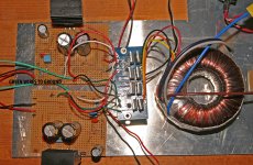
Are the little horizontal heatsinks at the top left and bottom left your chipamp heatsinks?
If so, they are far too small. They have less area than the bare rectifier diodes which only have to get rid of less than a couple of watts in total.
Use the National datasheet guide and then double what they recommend.
If so, they are far too small. They have less area than the bare rectifier diodes which only have to get rid of less than a couple of watts in total.
Use the National datasheet guide and then double what they recommend.
In regards to the mind blowing photo above, firstly, please keep all metal scrap at least eleven feet Away from your workbench.
And,
That is NOT a power supply board--that thing is a dual bridge rectifier board, same as 2pcs KBU1004 except for price. Where is the 0v?
It isn't on that board.
A problem is 0v tap for the power supply is either missing or not readily identifiable. See attachment for a remedy. It shows simplified grounding for Stereo builds with Audiosector power.
Attachments
Last edited:
- Home
- Amplifiers
- Chip Amps
- Beginner's Gainclone, HiFi LM1875, The Amplifier Board