Getting around to build this amp but I'm changing directions a bit. I'm going to build a mono version with one input to drive my office Altec A7. Can anyone suggest a volume pot value to use. I have a spare 100k log pot that I would like to use. Thx.
That might work. You might try adding 100k resistor load either in front or behind the pot. I can't remember which way. But try it. This does the nearer ideal value of 50k and can sound good at most locations on the dial instead of a narrow range. Wish I could remember if the resistor load goes in before or after the pot.
Hello Daniel- I sure am glad that this thread is still alive  and thank you for all your work in putting it together.
Having read through it I'm a bit confused about the components used. Is there a final BOM for this project. This will be my first non-kit build and I want to make sure that I order the right components. Should be fun.
and thank you for all your work in putting it together.Having read through it I'm a bit confused about the components used. Is there a final BOM for this project. This will be my first non-kit build and I want to make sure that I order the right components. Should be fun.
That might work. You might try adding 100k resistor load either in front or behind the pot. I can't remember which way. But try it. This does the nearer ideal value of 50k and can sound good at most locations on the dial instead of a narrow range. Wish I could remember if the resistor load goes in before or after the pot.
Hey Dan- I have the K50 kit that I'll be using. Can you provide the changes to this circuit with the 100K pot input into a 8ohm load.?
Thx!
Attachments
Yes.
Replace R1 with a variable resistor (made from a 1k trimmer, and connect its center pin to one of the outboard pins). This is a very useful low loss tone control; however, I think that the kit's arbitrary 1k fixed resistor is inappropriate. That part must be made adjustable. This area is a sort of a fine tuning to help balance out the other options.
Replace C3, R4, and R5 with something more sensible:
C3 will need to be larger value for quality bass.
Both R4 and R5 will need to be smaller values.
Apparently, the K50 designers compromised Every other audio feature in trade for a harmonically flat response. While we might accept some soundfield size compromise in trade for a no-shout tone, the overall lack of resolution in the k50 kit is inexcusable.
To get as close as possible to the K50 tone while increasing the resolution, change the R5, 180k to 110K (220k topside parallel with 220k trackside and minimized pin length for both).
That will incur the need of re-setting the gain. Once again staying as close as possible to the K50 tone, we need to stay with a small value for C3. Therefore, change C3 to 100u in parallel with a 10n polyester cap. After that, you can change R4 to 3.3K.
That's a decent gain and a slightly warm setting that will let you experiment with input cap (c1) size to adjust H1/H2 (cold/warm) harmonic bass balance.
The minimal mod in this post does not fix the soundfield size and likewise does not risk making the amp shouty. However, these minimal mods do increase the resolution, without really changing the K50's tone.
For more bass slam and higher resolution via decreased noise and decreased dc pollution of small signal, you can try changing R3 to 12k or even 10k.
This is not a balanced drive amplifier so, R3 and R5 won't match even if set to the same value, thus you don't need to match those two values for voltage, but rather the thing to match is Current and bear in mind that a small signal source pushes at R3 while a Power Amp pushes at R5, so a closer match for current always has R5 at a higher value and the amount that R5 should be higher (to decrease current) is affected by the proportion of the gain. The LTP will attempt to compensate, so the R3,R5 resistor values won't need to be different in same proportion as the gain, and therefore you'll have some exploring to do. Standard miller comp does have such caveats. I just wished to illustrate that these two values don't need to be the same value for a failed attempt for voltage match at the expense of ridiculous current mismatch. There's the output of a power amp pushing on only one of those resistors. SO, perhaps the news is different than with preamps.
P.S.
If you want to increase the soundfield size, you'll need to pull more feedback current by doing More of this: C3 will need to be larger value for quality bass. Both R4 and R5 will need to be smaller values.
You'll end up with something like 33K~75K (likely 47k~68k) range for feedback resistor, approximately 330u (more or less) for C3, and to fix the tone you'd end up changing both of the 220u power caps to High Quality 470u (or you can do 220u||220u if you have identical models of ordinary caps).
Just about every time you go for a bigger soundfield with an op-amp you'll also get a more shouty tone. So, the first step is to change the power caps up to a very high quality model of 470u to allow room for exploration. And then you try to discover the R4, C3, R5 combination that arrives at a make-break compromise in-between shout versus soundfield size. That is chosen suitable for your system, so I can't chose it for you.
However, I do suggest to "cheat" by making monoblocs because the fully independent units do a wider stereo separation which is indirectly helpful on the more difficult matter of soundfield size versus tone with op-amps. In some texts, soundfield size is vaguely called "imaging." And I really do suggest a head start by making monoblocs/dualmono. In my opinion, the price for the additional transformer and power supply is really worth it.
P.P.S.
As far as the 100K pot goes, it probably works fine; however, I'd suggest to attempt loading it down to a 50K value in some way or simply buying any old 50K pot. Simply put, 100k is lossy for resolution and bad for noise, 20k is dull but not noisy; however, 50k is an excellent compromise and fairly neutral. They cost about $2, so there's no need to use the wrong pot value.
Last edited:
Component List
I've re-read the thread and have done a copy paste of all the component recommendations. Could someone please let me know if I have missed anything
LM1875
A size TO220 Heatsink Insulator
Phenolic board (veroboard)
Resistors
27k
15k
820R
470R
2.2R
Capacitors
2 of 470uF 50v electrolytic
2 of 100nF ("104") ceramic
Whoops! Where's the input filter cap?
I forgot to list the 2.2uF capacitor.
*This can be a "made for audio" electrolytic or a "poly" capacitor.
Optional Component, input cable load
This is a 1M (1 megaohm) resistor.
This zobel shouldn't be within the audio band, but rather, just above.
For this, I've selected:
10R (10 ohms) and this one is brown, black, black,
plus
10nF, which is 0.01uF and probably has "103" printed on it.
Zobel. That's a resistor and capacitor, "RC," as a load.
This load is upon the speaker output.
Some spendy benefit is possible, at your option:
*You could purchase high quality 470uF capacitors for the amplifier board, and these are used along with the 100nF (0.1uF) that have already been shown at the amplifier board.
*You could also purchase a metal film 15k, or preferably, a 10k resistor for your Input Load because the all-band performance of metal film is desirable in a shunt role (and nowhere else in my design). The 10k option reduces DC offset.
*You could purchase whatever is typically used for Audiosector amplifier's DC input block (Blackgate "N"), and then you should omit the optional 470R compensation resistor.
*You should use 1w (or better) strength resistors for speaker zobel and also 1w strength for power supply board bleeder resistors.
-Except for those, the amplifier design is optimized for ordinary components.
Thanks
The old mixed/direct coupled design from post 1?
It offers the flattest response that a solo chip amplifier can do, and it has good clarity, but it has somewhat boring dynamics and slightly less durability due to the omission of the feedback-shunt cap. The caveats are typical of gainclones. The really flat response is not typical of a chip amp at all.
There were two patches for it:
Change the input load to 10k for decreased offset.
Up to 6600u output caps for speaker protector and longer lasting.
Both of the above are helpful for dynamics too.
I'll try to find the time to make a schematic for it.
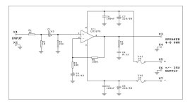
For the original at post 1, circa May 2008, here is a slightly revised schematic, with the updates, protection, and quality control patches added. I've also modified the speaker zobel to use 1/4 watt resistors for lower cost.
If it is your intention to crack the plaster rockin the house with an LM1875 chip, I would suggest to Avoid this mixed coupled design. Mixed/direct coupled designs provide a flatter response by omitting an important signal capacitor and that omission causes decreased dynamics and decreased durability. The design posted below is for near-field, mixer-desk, a point of reference, and for relaxing with a non-shout amp that has good resolution and a flat response. It is very helpful for near-field/mixing so that you don't accidentally overdo the audio compression on tracks.
The intended source is a computer sound card. The gain is rather high on this amplifier so that you don't have to turn the computer up high enough to strain/clip itself. This was thoroughly checked out with RMAA software and a very wide variety of computer chips and sound cards.
It does also need mains fuse and speaker jack fuse. Monobloc/dualmono is suggested so that you can somewhat control current via transformer selection and so that you can enjoy wider imaging.
Attachments
Yes.
Replace R1 with a variable resistor (made from a 1k trimmer, and connect its center pin to one of the outboard pins). This is a very useful low loss tone control; however, I think that the kit's arbitrary 1k fixed resistor is inappropriate. That part must be made adjustable. This area is a sort of a fine tuning to help balance out the other options.
Replace C3, R4, and R5 with something more sensible:
C3 will need to be larger value for quality bass.
Both R4 and R5 will need to be smaller values.
Apparently, the K50 designers compromised Every other audio feature in trade for a harmonically flat response. While we might accept some soundfield size compromise in trade for a no-shout tone, the overall lack of resolution in the k50 kit is inexcusable.
To get as close as possible to the K50 tone while increasing the resolution, change the R5, 180k to 110K (220k topside parallel with 220k trackside and minimized pin length for both).
That will incur the need of re-setting the gain. Once again staying as close as possible to the K50 tone, we need to stay with a small value for C3. Therefore, change C3 to 100u in parallel with a 10n polyester cap. After that, you can change R4 to 3.3K.
That's a decent gain and a slightly warm setting that will let you experiment with input cap (c1) size to adjust H1/H2 (cold/warm) harmonic bass balance.
The minimal mod in this post does not fix the soundfield size and likewise does not risk making the amp shouty. However, these minimal mods do increase the resolution, without really changing the K50's tone.
For more bass slam and higher resolution via decreased noise and decreased dc pollution of small signal, you can try changing R3 to 12k or even 10k.
This is not a balanced drive amplifier so, R3 and R5 won't match even if set to the same value, thus you don't need to match those two values for voltage, but rather the thing to match is Current and bear in mind that a small signal source pushes at R3 while a Power Amp pushes at R5, so a closer match for current always has R5 at a higher value and the amount that R5 should be higher (to decrease current) is affected by the proportion of the gain. The LTP will attempt to compensate, so the R3,R5 resistor values won't need to be different in same proportion as the gain, and therefore you'll have some exploring to do. Standard miller comp does have such caveats. I just wished to illustrate that these two values don't need to be the same value for a failed attempt for voltage match at the expense of ridiculous current mismatch. There's the output of a power amp pushing on only one of those resistors. SO, perhaps the news is different than with preamps.
P.S.
If you want to increase the soundfield size, you'll need to pull more feedback current by doing More of this: C3 will need to be larger value for quality bass. Both R4 and R5 will need to be smaller values.
You'll end up with something like 33K~75K (likely 47k~68k) range for feedback resistor, approximately 330u (more or less) for C3, and to fix the tone you'd end up changing both of the 220u power caps to High Quality 470u (or you can do 220u||220u if you have identical models of ordinary caps).
Just about every time you go for a bigger soundfield with an op-amp you'll also get a more shouty tone. So, the first step is to change the power caps up to a very high quality model of 470u to allow room for exploration. And then you try to discover the R4, C3, R5 combination that arrives at a make-break compromise in-between shout versus soundfield size. That is chosen suitable for your system, so I can't chose it for you.
However, I do suggest to "cheat" by making monoblocs because the fully independent units do a wider stereo separation which is indirectly helpful on the more difficult matter of soundfield size versus tone with op-amps. In some texts, soundfield size is vaguely called "imaging." And I really do suggest a head start by making monoblocs/dualmono. In my opinion, the price for the additional transformer and power supply is really worth it.
P.P.S.
As far as the 100K pot goes, it probably works fine; however, I'd suggest to attempt loading it down to a 50K value in some way or simply buying any old 50K pot. Simply put, 100k is lossy for resolution and bad for noise, 20k is dull but not noisy; however, 50k is an excellent compromise and fairly neutral. They cost about $2, so there's no need to use the wrong pot value.
Thanks again. This will be in my office system using Panadora for tunes thru our iPod. Found some 50k pots here...so just add it before the 1st resistor? Can I or should I eliminate any resistors? I want something down and dirty...build once and forget about it...let her play.
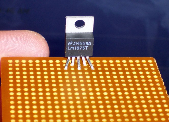
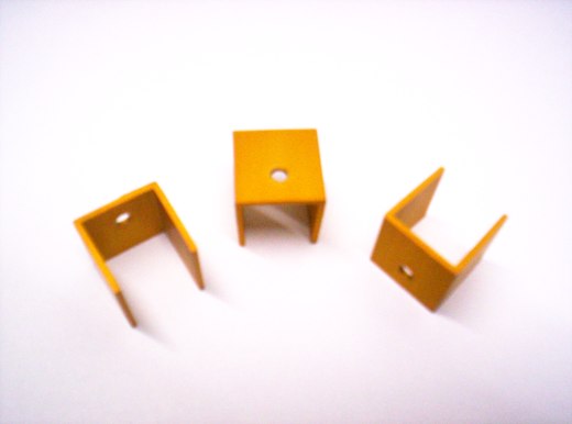
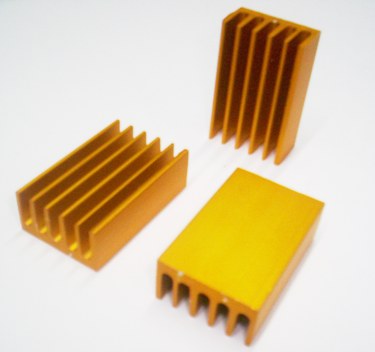
I know it's an old post, but am I the only one who turns "pentawatt" type chips forty five degrees, so they fit nicely in the 2.54mm 1/10" matrix and you don't have to stretch them as shown above?
Also, I had good results with lm1875 into (nominally) 4 ohms 88dB speakers, though not with this threads schematic or voltage.
Well, spreading their legs open doesn't hurt anyway.
Doesn't turn them 45º complicate mounting?
And yes, power is more than enough for home listening with typical "HiFi" speakers
I'm using a couple TDA2050 (which is about the same) as PC monitors.
Sure beats the "200W PMPO" 2" plastic speakers powered from the 5V USB connector
Doesn't turn them 45º complicate mounting?
And yes, power is more than enough for home listening with typical "HiFi" speakers
I'm using a couple TDA2050 (which is about the same) as PC monitors.
Sure beats the "200W PMPO" 2" plastic speakers powered from the 5V USB connector
Yeah, i;m probably a little OCD about finding that perfect fit. Doesn't really complicate mounting. I just cut the board diagonally if the sink is too big to sit on/above the board.Well, spreading their legs open doesn't hurt anyway.
Doesn't turn them 45º complicate mounting?
I beg your pardon?a response from anyone
I answered YOU in post #149
As of BOM, choose one schematic of the various posted and write a parts list down.
Less than 10 items anyway.
- Home
- Amplifiers
- Chip Amps
- Beginner's Gainclone, HiFi LM1875, The Amplifier Board