Awesome
I'm pumped! I need the lowest gain possible without compromising the overall sound. I use low output moving coil cartridges with step-up transformers. The gain add's up quickly between the preamp, SUT's and amplifier. It's quite a balancing act with my speakers. I also need the highest input impedance too.
I have some smps's at work that I can use. They're 75W 24VDC 3.2A
(adjustable) units so I'd like to use these initially until I can build some linear supplies.
Maybe a schematic would be easier than so much text.
Here's the basic idea on the K50 fixup. See attachment.
I'm pumped! I need the lowest gain possible without compromising the overall sound. I use low output moving coil cartridges with step-up transformers. The gain add's up quickly between the preamp, SUT's and amplifier. It's quite a balancing act with my speakers. I also need the highest input impedance too.
I have some smps's at work that I can use. They're 75W 24VDC 3.2A
(adjustable) units so I'd like to use these initially until I can build some linear supplies.
The range of feedback-shunt resistor is:I'm pumped! I need the lowest gain possible without compromising the overall sound.
3.9k 29x gain
4.7k 24x gain (shown on schematic at post 101)
5.6k 21x gain
6.8k 17x gain
7.5k 16x gain
8.2k 14x gain
9.1k 13x gain
10k 12x gain
12k 10x gain
*At some point the amp may need an input stopper resistor (series to in+) to help it restore balance.
**At low gain settings, external compensation may be needed.
If you have trouble with x-max when rocking the house, we can add a soft clipper to block x-max. They're in rough increments and would possibly require some really minor gain fine tuning to match up perfectly.The gain add's up quickly between the preamp, SUT's and amplifier. It's quite a balancing act with my speakers.
If you add series resistor, it will effectively give the preamp a lighter load and simultaneously "turn down the volume" which might be suitable if the amp has too much gain. Good spot to experiment with a variable resistor.I also need the highest input impedance too.
*Before trying for really light input loads on solid state electronics, most people would be using a buffer instead.
**The amp with the overly light input load will be extra sensitive to grounding and it will need extra attention to RF filtering. See the datasheet for some examples of the RF filtering.
Last edited:
If you have too much gain in the system, then maybe D's Buffer suggestion is a good one.
A Power Buffer instead of a Power Amplifier could be the way to go.
i.e. a power amplifier with a voltage gain of 1 (+0dB).
Another option and a good one. That would put my total system gain at a point where I can open up my volume pot. I can't get past 10 o-clock now.
I need to slow down a bit as I've been cramping nightly to try and catch-up with you guys. This is my winter project along with remodeling my master bathroom so I'll be jumping back and worth between the two.
Front End
How much of the front end I'm I going to retain from the K50. C1 & R3? What values?
Maybe a schematic would be easier than so much text.
Here's the basic idea on the K50 fixup. See attachment.
How much of the front end I'm I going to retain from the K50. C1 & R3? What values?
Attachments
Very fortunate choice of the k50 kit then. They're easy and fun. LM1875 has wide range tolerances (far easier to get "in the ballpark" when the ballpark is gigantic).lausar said:I need to slow down a bit as I've been cramping nightly to try and catch-up with you guys. This is my winter project along with remodeling my master bathroom so I'll be jumping back and worth between the two.
I wish I'd heard about this earlier. Excellent news! There's no need to lighten the power amp load until creating a noise floor at the power amp. What you need is a trimmer party. Slightly slower to build, but probably weeks or months faster for desirable end result.lausar said:. . . put my total system gain at a point where I can open up my volume pot. I can't get past 10 o-clock now.
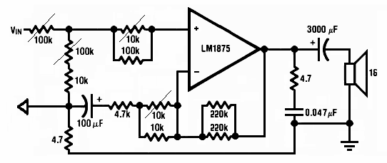
To convert a 3 pin trimmer to a variable resistor, solder the center pin to one of the outside pins--the trimmer now has only 2 pins which can be connected per the schematic. With that schematic, you can adjust during playback, which is a time-saver because it makes audio changes much more obvious and more easily comparable than powering off in-between changes.
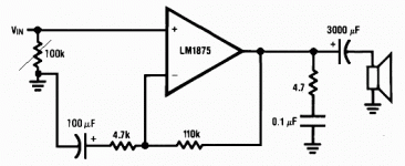
That depends on whatever the preamp/source wants. Since those specs are either missing or very wide range, see attachment. This schematic (attached) is designed to help you find optimal values quickly. If the preamp doesn't have an RC at the output, then you'll want to add RF filter (not shown) at the input of the power amp.lausar said:How much of the front end I'm I going to retain from the K50. C1 & R3? What values?
Here's your trimmer party: You listen and play with the dials while the amp quickly designs itself.

Tip: If there are several good choices, aim for that which runs coolest at the output RC's resistor and/or amp heatsink.
Attachments
Last edited:
I can't start the party- just yet.
I appreciate the help Dan but I can't see myself adding all the trimmers and finding the initial time to do all that tweaking, at least not this winter. I have to fiddle with my TT motor and build a new set of SUT's this winter too.
Can you get me started with a few values for the input section. I know it won't be optimal until I can find the time.
Very fortunate choice of the k50 kit then. They're easy and fun. LM1875 has wide range tolerances (far easier to get "in the ballpark" when the ballpark is gigantic).
I wish I'd heard about this earlier. Excellent news! There's no need to lighten the power amp load until creating a noise floor at the power amp. What you need is a trimmer party. Slightly slower to build, but probably weeks or months faster for desirable end result.
To convert a 3 pin trimmer to a variable resistor, solder the center pin to one of the outside pins--the trimmer now has only 2 pins which can be connected per the schematic. With that schematic, you can adjust during playback, which is a time-saver because it makes audio changes much more obvious and more easily comparable than powering off in-between changes.
That depends on whatever the preamp/source wants. Since those specs are either missing or very wide range, see attachment. This schematic (attached) is designed to help you find optimal values quickly. If the preamp doesn't have an RC at the output, then you'll want to add RF filter (not shown) at the input of the power amp.
Here's your trimmer party: You listen and play with the dials while the amp quickly designs itself.
Tip: If there are several good choices, aim for that which runs coolest at the output RC's resistor and/or amp heatsink.
I appreciate the help Dan but I can't see myself adding all the trimmers and finding the initial time to do all that tweaking, at least not this winter. I have to fiddle with my TT motor and build a new set of SUT's this winter too.
Can you get me started with a few values for the input section. I know it won't be optimal until I can find the time.
I'm doing my homework...
http://www.diyaudio.com/forums/chip-amps/207024-understanding-redesigning-input-stage-lm1875-3.html
http://www.diyaudio.com/forums/chip-amps/207024-understanding-redesigning-input-stage-lm1875-3.html
Just 3 trimmers are a faster trip to hi-fi than desoldering to swap parts. However, there are other options.I appreciate the help Dan but I can't see myself adding all the trimmers and finding the initial time to do all that tweaking, at least not this winter. I have to fiddle with my TT motor and build a new set of SUT's this winter too.
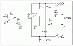
Your preamp has provided a great convenience with its excessive voltage output because that makes it possible to have the preamp see 124K load while the power amp sees 56K load. So, I've taken the post 101 design, guessed, checked it with an engineer and put it onto a K50-looking schematic for you. Since your preamp already has a cap, C1 is a solid copper wire and R2 is located at the power amp's RCA jack.Can you get me started with a few values for the input section. I know it won't be optimal until I can find the time.
See attachment. I believe it is "in the ballpark" and can get you "up and running" very fast.
Attachments
Lausar,I'm doing my homework...
Understanding and redesigning the input stage of LM1875
use the schematic in the Thread you linked.
Change R3 from 22k to 100k. That should get the output offset down a fair bit.
Change R1 to a film capacitor.
Add xxxpF across R3. Maybe from 330pF to 1000pF to suit your ears and your speakers.
Read the rest of the Thread and pay attention to the grounding and the different parts of the grounding.
Last edited:
Lausar,
use the schematic in the Thread you linked.
Change R3 from 22k to 100k. That should get the output offset down a fair bit.
Change R1 to a film capacitor.
Add xxxpF across R3. Maybe from 330pF to 1000pF to suit your ears and your speakers.
Read the rest of the Thread and pay attention to the grounding and the different parts of the grounding.
Thanks Andrew T.
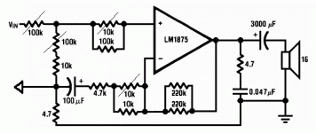
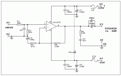
The attached schematic has nearly the same gain setting and ~100k input load but with your preamp's excessive voltage output put to good use--The amplifier sees significant feedback current and significant input load for higher resolution performance that relates to larger perceived soundfield and good stereo imaging. That's the difference.
Attachments
An early Xmas present...
I'll be ordering up the parts from Digikey and Mouser tomorrow but won't be able to get started until after Xmas. I'll keep you posted. It was a fun week cramming all this stuff in.
Thanks again Dan and to everyone else who contributed to the LM1875 threads!
The attached schematic has nearly the same gain setting and ~100k input load but with your preamp's excessive voltage output put to good use--The amplifier sees significant feedback current and significant input load for higher resolution performance that relates to larger perceived soundfield and good stereo imaging. That's the difference.
I'll be ordering up the parts from Digikey and Mouser tomorrow but won't be able to get started until after Xmas. I'll keep you posted. It was a fun week cramming all this stuff in.
Thanks again Dan and to everyone else who contributed to the LM1875 threads!
Some Panasonic for all of the caps at the amplifier board perhaps?I'll be ordering up the parts from Digikey and Mouser tomorrow. . .
P.S.
The actual 4.7u used across the rails is this model: http://my.mouser.com/ProductDetail/...=sGAEpiMZZMtZ1n0r9vR22e25txC9UcHAhF6LLFVMj9I= and it is installed directly from X5 to X7
The rest of the caps can be 50v tolerance for long life and preferably panasonic or nichicon (search diyaudio.com for favorites).
Last edited:
Some Panasonic for all of the caps at the amplifier board perhaps?
P.S.
The actual 4.7u used across the rails is this model: SEK4R7M250ST Cornell Dubilier | Mouser and it is installed directly from X5 to X7
The rest of the caps can be 50v tolerance for long life and preferably panasonic or nichicon (search diyaudio.com for favorites).
Thanks, I'm a Nichicon KZ and Elna Silmic II believer.
Some Panasonic for all of the caps at the amplifier board perhaps?
P.S.
The actual 4.7u used across the rails is this model: SEK4R7M250ST Cornell Dubilier | Mouser and it is installed directly from X5 to X7
The rest of the caps can be 50v tolerance for long life and preferably panasonic or nichicon (search diyaudio.com for favorites).
What's the 4.7uf used for?
The attached schematic has nearly the same gain setting and ~100k input load but with your preamp's excessive voltage output put to good use--The amplifier sees significant feedback current and significant input load for higher resolution performance that relates to larger perceived soundfield and good stereo imaging. That's the difference.
What will the gain be and can you give me the formula?
Just arrived (no, didn't read the 12 pages of posts) but curious: Why do you add unnecessary output capacitors in series with the speaker?.
Besides showing them as polarized in post #111.
Wiring them in antiparallel will not turn them into bipolars.
In post #114 you attribute no polarity to them, maybe hinting you'll use bipolars there.
I wonder where you will find 1000uF bipolars but even more what's the perceived advantage of adding them there.
AFAIK the Gainclone idea is to build a very simple very flat and clean "piece of wire with amplification" , and big electrolytics in series with the speaker do not exactly fulfill that task, at all.
Plus, as I said before, you don't need them, that split supply amp has 0V DC at the output.
And a polarized electrolytic is not happy at all (as in exploding with a loud bang) with AC across its terminals.
The gain in this case is (R5/R4)+1=(68/3.9)+1=18.4
- Home
- Amplifiers
- Chip Amps
- Beginner's Gainclone, HiFi LM1875, The Amplifier Board