By those changes, he's simply suggesting the datasheet schematic. Have you need of an 8 watt amplifier? That's when the datasheet schematic works well.Changes suggested by Andrew [in post 587] in blue text: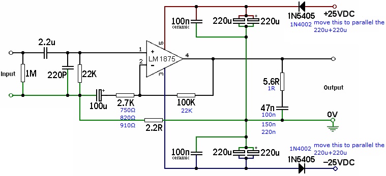
I suggest that you avoid changing the 1n5405; however, you can make their task more effective by adding 1 (one) 4.7uF 250v rated cap between the spots marked +25vdc and -25vdc.
Had the 2.7k been changed to a lower number, you'll need to change the 100uF to a higher number. You may have a hard time finding a really big cap of sufficient quality for audio coupler. However, here's a crude plan that will work. If you divided the 2.7k by three, then literally multiply the 100u by three (100u||100u||100u), which gets a little bulky but the quality should be good that way.
Had the 100k been changed to a lower number, you'll also want to change the +-25vdc to a lower number as well. Relating schematics to transformer voltage:
For the +-12vac (and less) transformer, use the LM1875 datasheet schematic
For the +-14vac and +-15vac transformer... well, who knows?
For the +-18vac transformer, use my LM1875 Turbo II schematic along with a current limited supply.
For the +-20vac (and greater) transformer, don't use any LM1875--chose a different chip.
No he doesn't..........Had the 2.7k been changed to a lower number, you'll need to change the 100uF to a higher number.
Look at the input filter. It is set to 48.4ms
Look at the NFB with 750r in there instead of 2k7. the RC=75ms. It exceeds input by more than sqrt(2).Even you eventually accepted that method of setting the ratio of input to NFB RCs.
This lot makes no sense.Had the 100k been changed to a lower number, you'll also want to change the +-25vdc to a lower number as well. Relating schematics to transformer voltage:
For the +-12vac (and less) transformer, use the LM1875 datasheet schematic
For the +-14vac and +-15vac transformer... well, who knows?
For the +-18vac transformer, use my LM1875 Turbo II schematic along with a current limited supply.
For the +-20vac (and greater) transformer, don't use any LM1875--chose a different chip.
Why should the NFB upper leg resistance be 100k?
Why should it need to be changed when supply rail voltage changes?
Why should anybody follow your ramblings when you don't follow any science based rules?
Last edited:
Perhaps I phrased it poorly, but it is remains true that if the resistor value is halved, the cap value must be doubled.No he doesn't. Look at the input filter. It is set to 48.4ms Look at the NFB with 750r in there instead of 2k7. the RC=75ms. It exceeds input by more than sqrt(2).Even you eventually accepted that method of setting the ratio of input to NFB RCs. This lot makes no sense.
Also, it will depend on the input filter.
And the whole matter will depend on the size of the speaker.
However, I already had this conversation with Tom of Neurochrome. He likes cold clear bass because of lowest distortion measured. Most people like warm bass. I require both simultaneously. So do you.
I this case, I must have had a language fault, again. Sorry about that.
Why should the NFB upper leg resistance be 100k?
 Because, insufficient derating in that example.
I'd like to take this moment to re-state that it does also require a current limited supply. That will probably incur the cost of making only monoblocs so that 1 supply protects 1 chip as precisely as possible.
Why should it need to be changed when supply rail voltage changes?
Because too much voltage in that example, has incurred a linearity pitfall, as has 22W on such tiny output devices. Obviously if a voltage amp doesn't work practically at a too-high voltage, but still doesn't break, then the problem is overcurrent.
I wasn't disagreeing with you on the need of more thoroughly derating the chip amplifiers even though I didn't exactly follow your advice. Instead I current-adjusted the resistor values and also used a current limited supply. And, so equipped, the very popular Turbo series survives abusive use.
Sure, they were going to do it anyway; however, your comments will surely have me remember that some annotation is required.
Current versus linearity is the applicable science thing--too much current = not enough linearity.Why should anybody follow your ramblings when you don't follow any science based rules?
The offset resistor values provide a functional compensation, which is Not necessary if the amp is derated properly.
Also, the Turbo and TurboII have been taking on all comers for over 7 years, and therefore a little scientific curiosity may be in order as to why.
Scientific principles are very like to work this way:
1). Make it work, any way that does.
2). Scientifically find out why it works.
3). Refine it to do better at what it didn't do well, WITHOUT reducing what it does do well.
4). Repeat all steps in order to achieve further refinement.
So, the objective and subjective are not at odds but rather they are inter-reliant, so that both are required.
I did bear in mind what you wanted, while working with the TDA7293.
An annotation is missing (Oh no! I did that Again???) from the following schematic--the printed gain is too high, on purpose, for first time startup stability/safety, but it can be dialed down to 33x, only if the board is the smallest one you can find. With the more powerful chip, I was able to trade away output power potential for, instead, increased resolution/3d/imaging. That was okay with the TDA7293, because 45 watts can still get awfully loud inside a normal size house (more is not required for small venue).
I had to derate down to a 45 watt amplifier to get the job done. However, the good news is that the filtering has made all of the 45 watts usable for music (CRC filtering, when and only if the loss is located at the edge of the amplifier board itself, will knock the sharp edges off of clipping while not at all reducing the useful output power--goodly bass comes from the reservoir and this does not hinder that). The parameters are far different than those of little preamplifiers, which are not required.
Note the inbuilt CRC, what with the decouplers and series loss of the diodes as well as the (assumed) offboard power supply, is effectively CRC and at that locale, cannot hinder the charge-up of the power supply reservoir (cannot hinder the bass power in any significant way).
Note the use of same||same cap bypass has robbed the the botique/snakeoil market of sales, which have been blocked by that method.
The 4.7uF is ideal with an modern ROHS-friendly Elna Cerafine Black; however, if you happen to have some destroy-the-earth era 10uF with the planet-busting chemicals, they'll do fine. Paralleled Elna Cerafine Black 4.7uF will probably be optimal; however, that would make the schematic look crazy (crazier?), and I had been trying for the opposite appearance. Wow, whatever--the deal is that if you can use a super-large input filter (with no advantage had one decreased it) then the amplifier's passband probably works well. It does. It took years.
The TDA7293 got 4 passes through the objective/subjective cycle; however, the LM1875 got only 3 so far.
The LM1875 Turbo II is overdue for an update.
I'd like to do another at +-20vdc, 15W, just to see if it is possible to improve both the safety (probably) and the imaging/resolution/realism as well. We're still probably not in need of that 8W design in the datasheet; however, I think that a 15W version could be doable without weird looking component values. That effort is extremely likely to cost cermet multi-turn trimmers, precision settings, the full T/S output pack and 5% resistor values, or tighter. At that point (of precision components), I get big questions about how likely someone is to do it. I think that it is not likely there would be a faithful copy. At some cost, including the likelihood of a wasted effort, it is possible to improve the imaging/resolution/3d/realism of the TurboII. That is a horribly tall order, and also, I'm grateful that you cussed me out for what it does not yet achieve. Thanks to your influence, a further refinement is likely. It will be a lovely challenge to make that practical. Thank you!!!!
Last edited:
and previously you came to accept the method of scaling the NFB capacitor: input capacitor RATIO to match the required passband frequency. Now you are trying to complicate by excluding that RATIO from your description.Perhaps I phrased it poorly, but it is remains true that if the resistor value is halved, the cap value must be doubled.
Also, it will depend on the input filter.
NO!!!! I want the audio signal to pass through complete and unaltered.And the whole matter will depend on the size of the speaker.
However, I already had this conversation with Tom of Neurochrome. He likes cold clear bass because of lowest distortion measured. Most people like warm bass. I require both simultaneously. So do you.
de-rate what? Are you introducing more fog to hide the real message?I this case, I must have had a language fault, again. Sorry about that.
what linearity pitfall? More fog?I'd like to take this moment to re-state that it does also require a current limited supply. That will probably incur the cost of making only monoblocs so that 1 supply protects 1 chip as precisely as possible.
What? more fog?as has 22W on such tiny output devices.
Obviously if a voltage amp doesn't work practically at a too-high voltage, but still doesn't break, then the problem is overcurrent.
I wasn't disagreeing with you on the need of more thoroughly derating the chip amplifiers even though I didn't exactly follow your advice. Instead I current-adjusted the resistor values
does it? Or does not enough current capability mean not enough current is delivered to the load?and also used a current limited supply. And, so equipped, the very popular Turbo series survives abusive use.
Sure, they were going to do it anyway; however, your comments will surely have me remember that some annotation is required.
Current versus linearity is the applicable science thing--too much current = not enough linearity.
Output offset is a different outcome. Why should it be compromised to fit your fog generator descriptions?The offset resistor values provide a functional compensation, which is Not necessary if the amp is derated properly.
I gave up reading this following paragraph.Also, the Turbo and TurboII have been taking on all comers for over 7 years, and therefore a little scientific curiosity may be in order as to why.
Scientific principles are very like to work this way:
1). Make it work, any way that does.
2). Scientifically find out why it works.
3). Refine it to do better at what it didn't do well, WITHOUT reducing what it does do well.
4). Repeat all steps in order to achieve further refinement.
So, the objective and subjective are not at odds but rather they are inter-reliant, so that both are required.
I did bear in mind what you wanted, while working with the TDA7293.
An annotation is missing (Oh no! I did that Again???) from the following schematic--the printed gain is too high, on purpose, for first time startup stability/safety, but it can be dialed down to 33x, only if the board is the smallest one you can find. With the more powerful chip, I was able to trade away output power potential for, instead, increased resolution/3d/imaging. That was okay with the TDA7293, because 45 watts can still get awfully loud inside a normal size house (more is not required for small venue).
I had to derate down to a 45 watt amplifier to get the job done. However, the good news is that the filtering has made all of the 45 watts usable for music (CRC filtering, when and only if the loss is located at the edge of the amplifier board itself, will knock the sharp edges off of clipping while not at all reducing the useful output power--goodly bass comes from the reservoir and this does not hinder that). The parameters are far different than those of little preamplifiers, which are not required.
Note the inbuilt CRC, what with the decouplers and series loss of the diodes as well as the (assumed) offboard power supply, is effectively CRC and at that locale, cannot hinder the charge-up of the power supply reservoir (cannot hinder the bass power in any significant way).
Note the use of same||same cap bypass has robbed the the botique/snakeoil market of sales, which have been blocked by that method.
The 4.7uF is ideal with an modern ROHS-friendly Elna Cerafine Black; however, if you happen to have some destroy-the-earth era 10uF with the planet-busting chemicals, they'll do fine. Paralleled Elna Cerafine Black 4.7uF will probably be optimal; however, that would make the schematic look crazy (crazier?), and I had been trying for the opposite appearance. Wow, whatever--the deal is that if you can use a super-large input filter (with no advantage had one decreased it) then the amplifier's passband probably works well. It does. It took years.
The TDA7293 got 4 passes through the objective/subjective cycle; however, the LM1875 got only 3 so far.
The LM1875 Turbo II is overdue for an update.
I'd like to do another at +-20vdc, 15W, just to see if it is possible to improve both the safety (probably) and the imaging/resolution/realism as well. We're still probably not in need of that 8W design in the datasheet; however, I think that a 15W version could be doable without weird looking component values. That effort is extremely likely to cost cermet multi-turn trimmers, precision settings, the full T/S output pack and 5% resistor values, or tighter. At that point (of precision components), I get big questions about how likely someone is to do it. I think that it is not likely there would be a faithful copy. At some cost, including the likelihood of a wasted effort, it is possible to improve the imaging/resolution/3d/realism of the TurboII. That is a horribly tall order, and also, I'm grateful that you cussed me out for what it does not yet achieve. Thanks to your influence, a further refinement is likely. It will be a lovely challenge to make that practical. Thank you!!!!
Fingernail sized amp, big speaker--there will be a caveat..de-rate what?
So, either you're going to hear a caveat or a compensation, whichever you prefer.
Sorry that I didn't address the rest of your post, but this was the necessary portion.
What caveat?Fingernail sized amp, big speaker--there will be a caveat.
Big speakers often means more efficiency than small speakers. So what has big speakers got to do with "Fingernail sized amp, big speaker"
So what is it that you think needs to be de-rated?So, either you're going to hear a caveat or a compensation, whichever you prefer.
Sorry that I didn't address the rest of your post, but this was the necessary portion.
remove the fog and tell us in plain english.
I was speaking of normal transducers. But, even if you weren't, the recoil from a big size cone as well as driving it, provides a probable way to destroy a tiny chip. Extensive derating could prevent destruction as well as simplify design.What caveat? Big speakers often means more efficiency than small speakers. So what has big speakers got to do with "Fingernail sized amp, big speaker"
The internal output transistors of the LM1875 are too small for the headline wattage figure and also too small for a 22W amplifier.So what is it that you think needs to be de-rated? remove the fog and tell us in plain english.
It could be a much finer quality amplifier, If also built to a smaller wattage scale.
That's also when you get a question, such as had you needed a much smaller scale amplifier. Apparently, I didn't.
Hi !
I would like to report my experiment with regard to posts501, 502, and 510
A little bit of modifications, i.e. all metal film resistors are 22k in series to form a 66k, however for the NFB, 22k + ((22k+22k)//10uF) to meet the 44k resistor parallel with 10uF. Rail voltages are +23V and -23V. The dc offset as measured at the output terminals are very small of about 0.001 volt.
It seems to have too much gain and produce unpleasant sound especially if the volume is high. This is not the case with the datasheet version which sounds wonderful.")
Any suggestions?
I have also experimented with 20k pot for volume control (it seems to work well with LM1875) and remove the input series cap (2.2 uF) because I am sure my source is equipped with output cap. The amp sounds better. I experimented with various inout cap I had, and they all sounded bad. I measured the dc offset is small of about 0.004 volt. Removing the input cap is not recommended if you are not sure that your source uses output cap.
Thanks.
I would like to report my experiment with regard to posts501, 502, and 510
A little bit of modifications, i.e. all metal film resistors are 22k in series to form a 66k, however for the NFB, 22k + ((22k+22k)//10uF) to meet the 44k resistor parallel with 10uF. Rail voltages are +23V and -23V. The dc offset as measured at the output terminals are very small of about 0.001 volt.
It seems to have too much gain and produce unpleasant sound especially if the volume is high. This is not the case with the datasheet version which sounds wonderful.
Any suggestions?
I have also experimented with 20k pot for volume control (it seems to work well with LM1875) and remove the input series cap (2.2 uF) because I am sure my source is equipped with output cap. The amp sounds better. I experimented with various inout cap I had, and they all sounded bad. I measured the dc offset is small of about 0.004 volt. Removing the input cap is not recommended if you are not sure that your source uses output cap.
Thanks.
At that voltage, ballpark gain range is likely within 28x~36x. If lower, it may sound like a hound, OR if higher it could get very boring. Search for these terms: Undercompensation and Overcompensation....+23V and -23V. ...It seems to have too much gain and produce unpleasant sound especially if the volume is high....
post510 sch should work just fine.
It has Dr Cherry feedback.
That extra 44k in the DC feedback allows the input leg to be increased from 22k to 66k (68k||1MVR) and that in turn allows a plastic film input capacitor instead of an electrolytic.
Can you measure the 1kHz gain?
or use the LF signal from Pano's test file?
Is this the first build since the February post?
100mVac at input should give 2.3Vac at output less a tiny bit for the loss across the RF attenuator (which is not shown).A simulation works fine with a gain of 23.
It has Dr Cherry feedback.
That extra 44k in the DC feedback allows the input leg to be increased from 22k to 66k (68k||1MVR) and that in turn allows a plastic film input capacitor instead of an electrolytic.
Can you measure the 1kHz gain?
or use the LF signal from Pano's test file?
Is this the first build since the February post?
Last edited:
Hi AndrewT,
Yes this is the first build. Apology for the delay.
The sound was like distorted sound, like "clipped sound" (I am not sure the correct English word for this), but higher volume, sound got worse.
Unfortunately, I don't have sufficient equipment to measure. However, the dc offset was small as I said. Now, I have removed the additional Cherry's feedback and use the datasheet circuit. It sounds good. So I think the chip is fine.
I will experiment with the circuit again, later. I still have more LM1875 with me.
Thanks for your help. I am gathering any thoughts and suggestions from you all to fix this.
Yes this is the first build.
Apology for the delay.The sound was like distorted sound, like "clipped sound" (I am not sure the correct English word for this), but higher volume, sound got worse.
Unfortunately, I don't have sufficient equipment to measure. However, the dc offset was small as I said. Now, I have removed the additional Cherry's feedback and use the datasheet circuit. It sounds good. So I think the chip is fine.
I will experiment with the circuit again, later. I still have more LM1875 with me.
Thanks for your help. I am gathering any thoughts and suggestions from you all to fix this.
Do you have a DMM that can be set to 199.9mVac?
Then measure the amplifier gain.
If your 10uF capacitor is broken, then the gain jumps from 23times to 67times. That's an extra 9.3dB of gain.
That will cause the problems you describe.
Did you reform your electrolytics?
Did you discharge your electrolytics, at least twice ?
Then measure the amplifier gain.
If your 10uF capacitor is broken, then the gain jumps from 23times to 67times. That's an extra 9.3dB of gain.
That will cause the problems you describe.
Did you reform your electrolytics?
Did you discharge your electrolytics, at least twice ?
Tonight, I had time to check your suggestion on my 22k//1k feedback amp to make sure I understand.
Can you verify my procedure of measuring the gain here, since the reading was really small? I measured the 22k//1k feedback amplifier, not the Cherry's one (that one has been disassembled for a while and will be rebuilt again later in my spare time and report back with the result. Because I needed the amp to work last Sunday so I decided to make the 22k//1k feedback)
1. I measured the ac input voltage, I got the reading of about 0.03 V (is it really this small?)
2. I measure the ac output voltage (speaker terminal), the reading was 0.64 V (is it really this small?)
So the gain is 0.64 V / 0.03 V = 21.3333
My feedback resistors are 22k//1k to the negative input of the chip.
About my 10uF cap, it is a non-polar type, a nichicon muse kz, so I think it should be good. I measured the capacitance, reading said it's 11 uF.
Thanks.
yes 30mVac and 640mVac does represent a gain of 21.33times.
It should read 23times +-(2times the +-1%) equals +-2% for resistor tolerances.
But does it have an RF attenuator at the input?
You need to take account of that.
eg 1k series into 47k to ground is 47/(47+1) = 0.9792
Your input is down to 29.375mVac
Multiply by your gain of 23+-2% and you get 676+-2% (i.e. anywhere between 662mVac and 689mVac), instead of 690mVac.
By coincidence if your input filter has values that match the feedback (1k and 22k) then the (22/1k)+1 gain cancels out and you get 22times.
Do the numbers and see.
Now consider what effect the input of 30mVac is +- a couple of digits.
Use a higher voltage, aim for 80mVac read from a 199.9Vac DMM scale and the output should be just less than 1.900Vac
Last edited:
At that voltage, the resistor figures (quite similar to the datasheet example) work very nicely.Oh, in case of someone interested in my speaker, I tested my amp (the one with 22k//1k feedback and 12-0-12 transformer, NOT the Cherry's NFB circuit) using these two speakers; Boston HD9 and ex-Philips MCL707. The bass is enough. Vocal is fine. Treble is nice.
At higher voltage, the linearity just packs up. As I was saying earlier, one possible working solution is to adjust the resistor values upwards so that the current isn't higher, even when the voltage is. That doesn't get very far, but it does a little. Anyway, try that Cherry example along with your power supply that has used the 12-0-12 transformer so that you're not making too many changes simultaneously. It is certainly nicer, more expedient and more informative to test-drive alterations upon examples that have already worked previously; and, especially when those are the examples that are supposed to work.
Last edited:
Hi Daniel,
Thanks for the suggestions. The reason I was in hurry making the new amp because the previous one with 12-0-12 was made a gift to my daughter. :-D So it is not mine anymore.
It's always nice to have someone who likes your work, right?
I have now another amp, with +/- 23 vdc and 22k/1k feedback. The PSU caps are large enough of 3x4700 uF per rail. This causes the vocal to be a bit moved back (um, difficult to say). I suspect it is due to large cap.
I am now in the making of another Cherry's FB amp. I'll report to the forum as I finished it. I'll do it P2P but will be very careful. I think I was a bit careless when doing the previous Cherry's FB amp and resulted in terrible sound.
Thanks for the discussion, especially AndrewT for his tutorial. I'll get back to you guys as soon as it's ready.
Cheers.
That doesn't match up; therefore, you may benefit from exploring other resistor values, really probably in direct proportion to the current increase. Have no expectation that it will sound the same despite having increased the voltage.. . .I have now another amp, with +/- 23 vdc and 22k/1k feedback.. . .
- Home
- Amplifiers
- Chip Amps
- Beginner's Gainclone, HiFi LM1875, The Amplifier Board