Mark, the three "grounds" in your diagram are all different.
Could you show three different symbols?
triangle, three bars and the E with a legend describing which is which.
I like the E for the Chassis, since in my head E = Earth, as in Protective Earth.
I use the three bars to indicate Power Ground. This tends to be the most commonly used by Members.
I use the empty triangle for the Signal Ground/Return.
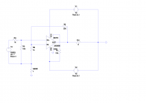
Schematics are made with LTspice and therefore more about doing stimulations than (ground) layouts. I also wanted to connect the resistors to a single point and make a star ground at the output but this was not possible.
And are they so different when you are talking about ground loops?
And are they so different when you are talking about ground loops?
Last edited:
yes.The GND of the opamp should have connected to Power Ground,
no.the other two are PE.
The source ground symbol is actually signal return. It does not get connected to the PE protected chassis. It's because it is the signal return that I recommend that it deserves a different symbol. That avoids the confusion caused by adopting the same general "ground" for everything.The source is connected to PE and the amp is connected to PE.
The one one the far right is on the other isde of the GLB. This ground is actually the PE protected Chassis. Again it avoids confusion when a different symbol is used to define it's uniqueness.
AndrewT, you are not understanding the schematic. The signal return has already been drawn, it runs from V4 to HBRR. The source has it own connection to PE as it is CLASS I and has its own chassis.
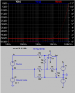
What Daniel has done is to add a voltage in the ground loop to simulate the hum at the output. It would be interesting if he could do simulations of the different configurations.
What Daniel has done is to add a voltage in the ground loop to simulate the hum at the output. It would be interesting if he could do simulations of the different configurations.
It is the dual channel pre-amplifiers that will benefit from a HBRR and HBRL to help attenuate the interference current in the pre-amplifier circuits.
It's not the GLB, or lack of it, in the source box that is the problem.
This only becomes a problem if there is a direct connection from Source Power Ground to Source Chassis. Many do not have this connection.
It's not the GLB, or lack of it, in the source box that is the problem.
This only becomes a problem if there is a direct connection from Source Power Ground to Source Chassis. Many do not have this connection.
That is correct, but wasn't on the topic. Both preamplifiers and voltage amplifiers too.It is the dual channel pre-amplifiers that will benefit from a HBRR and HBRL to help attenuate the interference current in the pre-amplifier circuits.
That's exactly the topic. And, I'd like to add that modern sources, probably the majority, usually Are a problem.It's not the GLB, or lack of it, in the source box that is the problem.
And then, what do we do? Earmuffs? Probably.
However, let's make a change. Few do, but those sound awesome!
Shameless plug: Turbosound concert amplifiers (carry on a conversation without strain despite trouser flapping bass). I always ask who made the stuff at concerts, but only if they done it right. Those guys did! I only ever asked twice. It was the same answer. Have you ever asked?
That is simultaneously wishful thinking and most excellent advice.This only becomes a problem if there is a direct connection from Source Power Ground to Source Chassis. Many do not have this connection.
Indeed we should buy better sources, and a really minuscule amount are available any every price point. Availability is pitiful and should not be assumed. I only found one in these many years--the PT810 bluetooth device, which is barely up to CD specs, is in the "econofi" class (entry level for authentic hi-fi) and is extremely close to sufficient. I mailed one to Elvee for diagnosis. He thought that my description of it was fair, if colorful.
Indeed it was effective that wireless prevents ground loops so that noise is not significantly conduced through the air.
As we know, a step beyond CD specs involves 24 bit audio, which could sound better so long as the source doesn't make too much noise. Where the heck are those? Tell me!!!! I think that they're either rare or cost more than my car. Either that or they're not effective at all, which is usually the case (I'm not at all trusting; and, therefore, I'm reliant on proof).
Therefore. . .
It could be of some value if the amplifier could (at very slight cost to itself) reduce some of the noise from a typical modern source. Currently, that is the topic. . . not actually to make the amplifier work better but rather to make the source work better because of amplifier mods.
The question is. . . is that of greater value than its costs.
And, we didn't find out yet.
P.S.
The current balance load/tilt thing that I posted earlier is nothing other than a sure-fire way to find out if you should have derated your amplifier to bring it up to specs. Derating would have avoided an impassible compromise of that imaging versus tone problem. You can have both very fine at the expense of output power. It is pretty much the triangle graph there (the points being output power, imaging, tone), and then choose only two.
P.P.S.
Please resume cussing me out by degree of severity. That was ever so appreciated, because informative. And, I really miss it. So far as the speed of education goes, that was of maximum efficiency. Even though some of that was coarse to hear/read, I am in your debt and am grateful. Thank you.
Or even better:
Mark, I'm sorry that I couldn't make sense of #561, but #562 is understandable as a current drive device, which would make full-range and mass market speakers probably sound fantastic. . . However, my speakers with the Devore crossover (hybridized first series) have current drive inbuilt into the speaker cabinet for enhanced compatibility with zero ohms output impedance amplifiers--the majority of solid state--at slight cost of incompatibility with tube and other current drive amplifiers, including yours.
I was pretty, but I'm sorry that I couldn't make sense of it. The topic of how to do better than good always has such costs. Even so. . . Halp???
There is no current drive aspect to this design. Only a control of ground loop currents and voltages.
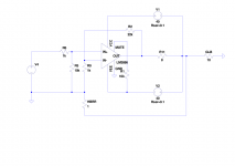
If all Class I AV equipment was designed this way there would be a lot less ground loop problems.
Just connect the output returns to 0V (GND) with a GLB to PE and a resistor separating each input GND and 0V (GND).
If all Class I AV equipment was designed this way there would be a lot less ground loop problems.
Just connect the output returns to 0V (GND) with a GLB to PE and a resistor separating each input GND and 0V (GND).
danielwritesbac: you've built an amp based on the TDA7297, so, in your opinion which sounds better [yeah, yeah I know it's subjective, but still...]? One of these [in this thread] LM1875 implementations or the one you built based on the TDA7297? I'm looking to build a low part P2P amp which is a step up from the TDA7297.
- Home
- Amplifiers
- Chip Amps
- Beginner's Gainclone, HiFi LM1875, The Amplifier Board