Polarized caps. . . if these happen to preserve the amplifier then nothing breaks, but if something does go very wrong, there's about a 50/50 chance the cap will break and somewhat less chance that it may fail to protect the speaker.
Bipolar caps (or high quality bipolar assembly). . . doesn't break even if the amplifier does. And if run this way, an LM1875 broken in the most typical failure mode (large dc offset), will actually continue to play as if there was nothing wrong. The bipolar assembly schematic shown earlier is sized for a maximum size speaker; however, a smaller speaker can (and should) use less capacitance.
Either way is a good effort towards protecting a speaker (and costs less than speakers), plus the bonus features of bass tuning (size filter appropriate for Your speaker) which always comes with at least a little bit of headroom enhancement.
Last edited:
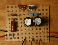
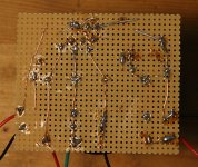
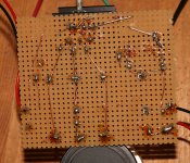
Well- I have managed to get one board completed after a couple attempts. ") Problem is it sounds really bad- very crackly and cuts in and out. It's worse at lower volumes. I have tried 3 different speakers and 2 power supplies. I don't have the proper power supply yet so I tried a 12v meanwell and a 18v wall wart.
Problem is it sounds really bad- very crackly and cuts in and out. It's worse at lower volumes. I have tried 3 different speakers and 2 power supplies. I don't have the proper power supply yet so I tried a 12v meanwell and a 18v wall wart.
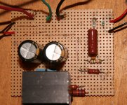
I have checked it over against Daniels photos several times but can't find anything wrong with it. Could someone kindly take a look at my photos and tell me what might be wrong. I haven't cleaned it up yet so forgive the flux mess
cheers prezden
Problem is it sounds really bad- very crackly and cuts in and out. It's worse at lower volumes. I have tried 3 different speakers and 2 power supplies. I don't have the proper power supply yet so I tried a 12v meanwell and a 18v wall wart.I have checked it over against Daniels photos several times but can't find anything wrong with it. Could someone kindly take a look at my photos and tell me what might be wrong. I haven't cleaned it up yet so forgive the flux mess
cheers prezden
Attachments
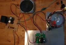
The heatsink is missing!!!
And that amp does require split rail power, not a wall-wort.
Cutting in and out is the overload protection running, and the sounding really bad is your speaker cooking.
P.S.
That amp is incomplete and can't function right because. . .You need a heatsink, a center tap transformer, a bridge rectifier, and some caps for a power board.
Last edited:
Thanks Daniel. I was anxious to hear how it sounded and so hooked it up to what was at hand. I do have a couple toroidal transformers one being 9-0-9 and the other 30-0-30. Neither one the right size. I also have a couple small rectifier boards. I'm guessing it be best to test it with the smaller transformer?
This project is quite a challenge after building a few simple kits. More fun too.
cheers
This project is quite a challenge after building a few simple kits. More fun too.
cheers
Daniel last year I tried lm1875,, it was very musical but very noisy..This is my own tests and observation.
Surprisingly I could not build a lm3886 amp from that same power supply.It always turn so hot eventually it fuses.I had a power imbalance of about 1volt.May be something went wrong with my schematics.
By the way cant we use a 10K pot for that 1M resistor.
Surprisingly I could not build a lm3886 amp from that same power supply.It always turn so hot eventually it fuses.I had a power imbalance of about 1volt.May be something went wrong with my schematics.
By the way cant we use a 10K pot for that 1M resistor.
Ideal for an LM1875 with an 8 ohm speaker:
18+18vac, either 1 ampere dual secondaries transformer or 1.5a center tap transformer.
Ideal for an LM1875 with a 4 ohm speaker:
12+12vac 2a center tap or 13.5+13.5vac 2a center tap.
and,
These lower voltage transformers (which can be found everywhere) also work for use with 8 ohm speakers--with lower voltage you wouldn't get all of 25 watts, but you will get a working amplifier.
You can find the 24vct (12+12 center tap) at many places, such as the hobby shop or hardware store. On this popular EI core (square), there usually "12, 0, 12" stamped or marked on it, so you can identify it easily.
Ideal bridge rectifiers:
KBPC1002, KBPC1004, BR84
These lovely square things have all of the contacts very well marked so there's no confusion.
Ideal AC cable from transformer to bridge rectifier:
18ga or 19ga multi-strand Alloy (silver color)
Normally comes free with transformers and computer supplies too
Flux is necessary for successful soldering.
Ideal DC cable from power board to amplifier board:
20ga solid copper (orange color)
Bell wire, Thermostat wire. About 7 inches. Twist tight, and put a knot (or FB73's) in at the edge of the amplifier board. This stuff filters off noise and unnecessary peaks nicely.
Noise?Daniel last year I tried lm1875, it was very musical but very noisy.
. . .I had a power imbalance of about 1volt.. . .
That is probably build error, but it could be Source.
Amplifier will make much noise if your input load is incorrect. Mine are silent at full blast and without a pot. The Post1 design is for near-field studio mixer use (also works at computer desk). Audible noise output is Zero.
If the phenolic build was too difficult, know that you can "transplant" most designs onto LM1875 Kit boards, for an easier build.
Some sources could benefit from a buffer, and the only way to know is do it and find out if you get a surprise of really rockin bass and clearer, more level sounding audio; and, the need of adding a separate buffer project is because of a source with insufficient output parts, not because of an amp.
Volume pot: 10k~20k is dulling but 100k is noisy, so use 50k for an imperfect answer that happens to work. I avoid them all when possible. A volume pot cannot successfully drive with the signal intact if there's a cable at output longer than about 7" so an ideal spot for a volume pot is at the input of a buffer and located ON, soldered onto, the same board as the buffer. A volume pot can successfully drive a buffer and then the buffer can drive whatever you want, such as cable > power amp.
It seems that adding a volume pot is the #1 most popular way to cause the need of a buffer. OOPS!! And, you might not need to do it that way.
Actually the LM1875 at post 1 is very unlikely to need either a volume pot or a buffer. Removing the volume pot also removes the main need of a buffer. Volume pot is an "integrated amp" component that doesn't belong on a "power amp" ever. Volume pot belongs on a buffered preamp or preamp board and if you don't have those parts, don't install the volume pot either. That's simple, isn't it?
Just plug in your PC. If that's too noisy, plug in a Wolfson DAC USB board with separate power supply that has a 2-prong cord. The kits are not expensive. Also, there's Iriver H10+RockBox added, which has a Wolfson onboard, a cheap price on used market and can probably play a lot better than a laptop PC. Wolfson does decrease fuzz. Also, it understands WavPack in lossy version, which also decreases noise (sends it into a secondary file that you won't need) and 350k rate 24 bit is about as transparent as lossless, competes with Flac and leaves MP3/MP4/AAC in the dust. Wolfson DAC playing WavPack is a sonic delight, and not expensive.
Unfortunately, an amplifier as good as the LM1875 can reveal that your PC source is probably a noisy mid-fi source. And using a volume pot to throw away more music than noise, is counterproductive at best. If you want more rocking and less revealing, try my TDA7294 projects (or other latfet outputs amplifier), which are quite clear but their purpose is more for pleasant loud replay, not for studio mixer.
Between these two different types of presentations (highbrow vs tone amp), having your cake and eating it too may be something like Nico's Latfet version of the SSA amplifier, which is a shunt comp type and those do well at hiding noise floor while not hiding music. Tip: Pay more attention to the power circuit than to the amplifier, and in that case, the amplifier has a chance of doing what you want.
Lopsided voltage?
That is probably Transformer Error.
If you convert a single bobbin EI core to a dual secondaries, lopsided voltage results. If you convert a dual bobbin EI core to a dual secondaries but used copper hookup wire, lopsided voltage results. If you convert a dual bobbin EI core to a dual secondaries and use alloy hookup wire, that works.
For example, the Allied Electronics store brand of 36.0vct (marked 18,0,18) 1 Ampere center tap transformer. That's almost perfect but not quite strong enough. It is dual bobbin, and that means it is okay to convert it. So, I cut the center tap cable in half, and used the extra piece (of proper alloy hookup wire) to convert the transformer to dual secondaries.
Now I have a Hammond 18+18 1a dual secondaries transformer at half price. YAY!!
Single bobbin has two insulators--there is one on each end. Don't convert it!--leave it a center tap and use it normally.
Dual bobbin has three insulators--there is one on each end AND there is one in the middle too.
If your dual bobbin transformer is slightly undersize on amperage for your application, you may choose to convert it to a dual secondaries. Be sure to use the same type of alloy hookup cable that comes with the transformer. Add some heat shrink tubing and automotive heat-worthy glue, as needed for safety.
Still lopsided?
If at end result, you've still got up to 1.5v lopsided, and if that is a dual secondaries supply (has 2 bridge rectifiers), add a variable RC (50R trimmer, 2u cap) from "~" to "~" right at whichever one bridge rectifier has higher voltage. That's the AC secondaries side of the transformer, which makes a signal of really terrible quality. Turning down power noise is a most elegant way of leveling out your voltage. This will also make at least half of your dual secondaries power supply conform to high end standards.
And, turning one dial is easy to do.
If that doesn't cut enough voltage, add 10nF polyester dip (not box) caps parallel to every diode (you need 4 little caps) of whichever bridge rectifier is loudest (highest voltage), that will cut off some more noise and therefore decrease voltage slightly.
Still yet lopsided?
Put a standard diode, such as 10a05 in series with your DC power, preferably right after the first or second caps in your power supply. This is a crude and makeshift way of dropping about 0.6vdc from the too-high side of your power supply. It wouldn't be suited for a first try, but if you already tried everything else, then a diode drop will do the job as a sort of band-aid like patch. Perhaps it would cut the discrepancy down to less than 1v. Of course we should try all other more elegant means before considering a patch like that.
Last edited:
So it seems im having a psu issue. Im using an avel y23 series at 18 0 18. When testing the secondary across the ac im getting 20 20. a little high, but thats not the issue. When i test the DC from rail to ground at the rectifier i get 27 per rail! what is happening here?
the transformer hookup is parallel at primary, series at secondary with the orange and red tied for my 0 line.
the transformer hookup is parallel at primary, series at secondary with the orange and red tied for my 0 line.
So it seems im having a psu issue. Im using an avel y23 series at 18 0 18. When testing the secondary across the ac im getting 20 20. a little high, but thats not the issue. When i test the DC from rail to ground at the rectifier i get 27 per rail! what is happening here?
the transformer hookup is parallel at primary, series at secondary with the orange and red tied for my 0 line.
DC voltage of 27,0,27VDC is what an 18,0,18VAC transformer + power board will do in the USA.
It is appropriate.
That is an excellent head start.
The 20vac is not appropriate. You've got excess power supply noise. The bridge rectifier and transformer are yelling at each other and kind of like a ping-pong effect, that's causing ringing. Simply put a 50R trimmer + 2u polyester cap, a variable RC, from "~" to "~" (one RC across the transformer secondary, does not hook up to the 0v) right direct at the bridge rectifier location. There's many ways to adjust that dial, but fortunately it is an audio amp power supply, which has a specific task to do, so just adjust the dial for prettiest, most open sounding treble. Other way to adjust for practical benefit is take heatsink temp, subtract room temp, and that gives you amp waste heat figure--set for least heat output.
Once the setting has been adjusted towards some sort of benefit, it does not need to be readjusted unless you replace either the transformer or bridge rectifier.
If the power noise is especially fierce, such as 50 apartments all on one line, then you'll need 4 of 10nF polyester dip (not box) caps. Those are installed at 1 parallel each diode of the bridge rectifier. Mark Houston shows us how:

If your treble goes a bit dull, change the 10nF caps to 4.7nF.
The cap per diode is not really compatible with fast or stealth diodes, but works fine with standard silicon diodes and prefab bridge rectifiers. This diode snubbing can be used in addition to the variable RC mentioned earlier.
Alternative method: Center tap transformer > one variable RC across the secondary > Fairchild Stealth bridge rectifier > CRC power board.
If you can take off 1v worth of noise (cut the noise in half), it will be just about perfect.
Question: How many transformers and what amperage?
Thanks, It is 230 va 18 0 18. I think it will provide as much as 6a. Im going to use it for both boards.
The 20vac im getting is measured at the secondary winding terminal. However, i will try the RC on the rectifier as shown. The rectifier is an NTE Bridge rectifier (singe phase) rated at 200v 8a.
However, what could cause 7vdc at the speaker output? This seems unreasonably high. It nearly cooked the wirewound 10 ohm dummy load i out on it (burned me when i touched it). I cant imagine my speakers would have been happy.
Fred,
have you powered up via a bulb tester?
Keep this bulb tester in circuit until AFTER you have completed all tests and proved you have everything wired up correctly.
Have you powered the transformer alone and checked you have it wired correctly?
Have you powered up the transformer and rectifier and checked you have it wired correctly?
Have you powered up the transformer, rectifier and smoothing capacitors and checked you have it wired correctly?
Have you powered up the transformer, rectifier, smoothing capacitors and one channel of amplifier and checked you have it wired correctly?
Have you shorted the amplifier input and checked you have near zero output offset?
Have you measured the output noise with the input short in place?
Have you removed the input short and re-checked the output offset and output noise?
Have you connected your source and re-checked the output offset and output noise?
Have you tried moving the volume control and switching the source off and on and checked the output offset during al these changes?
Now you are ready to connect a dummy load.
Last edited:
Hi Daniel
Well I seem to have something buggered up. I've connected the amp boards (have 2 completed now) to a 9V transformer and rectifier. I know that's not enough to properly drive these amps but I would think it would be enough to get some sound. There is 11.4v reaching the board. Problem is there is no sound at all on either board. I think some of the components may not be right. I followed the label on the bags from DigiKey but they don't look the same as on your photos.
Any suggestions please
Well I seem to have something buggered up.
I've connected the amp boards (have 2 completed now) to a 9V transformer and rectifier. I know that's not enough to properly drive these amps but I would think it would be enough to get some sound. There is 11.4v reaching the board. Problem is there is no sound at all on either board. I think some of the components may not be right. I followed the label on the bags from DigiKey but they don't look the same as on your photos.Any suggestions please
Attachments
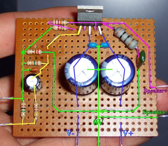
I see that the small signal corner of your amp board still hasn't been fitted with NFB-Shunt Cap. And because of that omission, the chip may be broken easily by power mistakes.
You need to cut the connection from the 820R to ground and patch that cut with a 470u (or 220u||220u for higher quality) capacitor as shown on the schematic at post 1. Have a look.
Signal can cross that capacitor, but DC does not. Blocking DC there, prevents amplification of DC. The layout has a big blank space on the corner where you should install this cap. Do it soon! You need it!
Introducing. . . Split Rail power. (typical of home audio amplifiers)
Have a look at a 2-battery flashlight.
It has a negative side battery and a positive side battery.
Centerpoint is equal and opposite force, which is 0v.
The LM1875 design that you're using requires at least +8V, 0V, -8V, DC power source, and 3 conductor cable to the amp board.
For reference, max is +27V, 0V, -27V, DC power, and of course, 3 conductor cable to the amp board.
Have a look at the following materials (attached)
Attachments
- Home
- Amplifiers
- Chip Amps
- Beginner's Gainclone, HiFi LM1875, The Amplifier Board