Antonio, your experience is precisely why I recommend P2P for building chip amps.
With P2P, you see exactly where the wires go, and a quick check will usually reveal any errors. When you use a board, the connections are on one side and the components on the other so it is much harder to visually inspect that everything is where it should be and connected properly.
You shouldn't have damaged anything when you took it apart although only you know how much heat you applied, and for how long it was applied.
If you did reverse the connections from the rectifier, it is likely that you will have damaged the polarised caps. Do they show any signs of bulging?
Nuuk,
I did not explain myself well. I have used a plain perforated board so in fact the new build is also p2p and I can clearly see how and where everything is connected
The caps does not show any sign of burning.
AndrewT,
I did not perform the light bulb test the second time but the rectifier board was built separately and I did not touch it between the first successful attempt and the unsuccessful one. I did test the bridge with the did tester and everything seemed ok.
Nevertheless, I will do the light bulb test as suggested.
Thanks for your help.
Regards
Antonio
Ps Any answer to the question of whether the chip can be tested with a multimeter and how?
Nuuk said:
If you did reverse the connections from the rectifier, it is likely that you will have damaged the polarised caps. Do they show any signs of bulging?
Nuuk,
I used the rectifier as shown here:
http://dogbreath.de/Chipamps/GainCardCopy/GainCardCopy.html
I notice that in the rectifier the V+ and V- are really mirror images and it seems that that it would not matter connecting them either way to the chip.
On the other hand the caps where connected correctly in terms of polarity and chip pins.
Anyway I will start all over again as I am surely missing something.
Regards
Antonio
A Sanchez said:I notice that in the rectifier the V+ and V- are really mirror images and it seems that that it would not matter connecting them either way to the chip.
Hi Antonio.
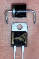
It matters. Try a 1 piece rectifier (clearly marked, like KBPC1004), or have a look at this PDF: http://electronics123.net/amazon/datasheet/k114.pdf
See the polarity of the rectifier?
MUR860's? Oh heck! Well, have a look at this picture.
Attachments
Re: RE: Post # 302
That's ironic, in a way. Today, I was de-soldering MUR860's to replace them with quiet, 1 piece, commercial block rectifier.
Bluto said:Good point and I think a link to that ought to be in any instructions.
Bluto
That's ironic, in a way. Today, I was de-soldering MUR860's to replace them with quiet, 1 piece, commercial block rectifier.
danielwritesbac said:
Hi Antonio.
It matters. Try a 1 piece rectifier (clearly marked, like KBPC1004), or have a look at this PDF: http://electronics123.net/amazon/datasheet/k114.pdf
See the polarity of the rectifier?
MUR860's? Oh heck! Well, have a look at this picture.
Dan,
Many thanks for your comments.
My local supplier sells the KPBC rectifiers but not the KPBC1004. Here is the list of what they have: http://www.maplin.co.uk/Module.aspx?ModuleNo=19088&C=5716&U=article_shopping_list_35_AQ98G
Could you tell me if I can use another model?
Are KBPC one piece rectifiers as good as building the rectifier with MUR680s, whcih what everyone seem to recommend?
Regards
Antonio
no,A Sanchez said:Are .... one piece rectifiers as good as building the rectifier with MUR680s, whcih what everyone seem to recommend?
not everyone recommends.
Many builders use the normal commercial rectifier bridges available in ratings from 1A to 35A.
Are KBPC one piece rectifiers as good as building the rectifier with MUR680s, whcih what everyone seem to recommend?
A typical question answered here .

A Sanchez said:
Dan,
Many thanks for your comments.
My local supplier sells the KPBC rectifiers but not the KPBC1004. Here is the list of what they have: http://www.maplin.co.uk/Module.aspx?ModuleNo=19088&C=5716&U=article_shopping_list_35_AQ98G
Could you tell me if I can use another model?
Are KBPC one piece rectifiers as good as building the rectifier with MUR680s, whcih what everyone seem to recommend?
Regards
Antonio
Oh you're welcome.
On that list, the KBPC1005 will be the most clearly marked of the suitable 1-piece rectifiers.
AndrewT said:no,
not everyone recommends.
Many builders use the normal commercial rectifier bridges available in ratings from 1A to 35A.
Hi Andrew! Thanks so much for your help. I have a diode question. I kept trying, and trying to fix my tuner, without much luck. Finally I got it up to 3 somewhat clear stations and one slightly staticy. After I replaced my MUR860's (with a bloc rectifier), now my tuner gets 36 FM stereo stations instead. What a nice surprise!! Was there something extra I should have done to help the MUR860's? Well, I got that thing fixed, but now I'm curious.

Nuuk said:
Thanks Nuuk,
I just keep going back to your site for well explained answers and I have to say that in fact your page has virtually everything one needs to now to build basic or complex gainclones, and much more...
Your site is a tremendous effort which is greatly appreciated.
Best regards,
Antonio
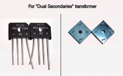
Do you have a "Dual Secondaries" transformer?
This has four wires output instead of the simple 3 of the center tap.
I've worked for something simple, because the usual hookup method (eight seperate diodes) for a Dual Secondaries is confounding to the eye.
Not anymore.
This has four wires output instead of the simple 3 of the center tap.
I've worked for something simple, because the usual hookup method (eight seperate diodes) for a Dual Secondaries is confounding to the eye.
Not anymore.
Attachments
danielwritesbac said:By request, here it is:
Beginner's Gainclone with
LM1875. . .
Here's the thread for it: http://www.diyaudio.com/forums/showthread.php?s=&postid=1513046
The LM1875's easier hookup should go quite well. Let's find out.
Thank you
I am an audio beginner, few months registered at diyaudio, and I want to thank you all partecipants to this thread and in particular Daniel and Peter for they new threads on step-by-step building of a chipamp and Decibel Dungeon for its web-page dedicated to gainclone full of information.
I am waiting for the kit I ordered at Audiosector (Peter has been very kind and he gave for free the pcbs as promised to the partecipant at this thread).
My contribution can be the feedback from a genuine audio beginner. Unlikely in this period I do not have sufficient free time, so my progress will be very slow.
Thank you again
Northernsky
Hello again,
I will have the PSU in a separate box and will be using two transformers and have been looking for a way to be able to easily connect/disconnect the electrical cables between the boxes. Could anyone help me with the name/type of connectors used for this purpose ( a sort of screwable multicoaxial chassis mounted female/male connectors. I have looked on the internet and have not found a clear answer and in Maplin (the UK Radio Shack) they told me to use aerial connectors assuring me that they can handle electricity as well (but this sounds dodgy in principle).
Many thanks
Antonio
I assume that you will be using a dual mono PSU and I suggest using two switches to enable you to turn each channel on and off separately. And I suggest two umbilical cables too so each each one will have four or five wires in.
I have used Farnell Order Code: 1077724/1077728 in the past although you are limited to smaller sized wires. Order Code: 3841157/3840876 look to take larger wires but I have not used them myself. Basically you need to search for a multipole plug and socket.
You only need to have an earth wire in one of the umbilicals unless you use separate amp cases too.
Use flying leads from the PSU case(s) with a suitable sized cable gland to hold the umbilical securely.
re power cable connectors. I have been contemplating the same thing - dual mono amps, connected to a box with two transformers, four bridges, V+,V-, and two grounds to each amp (twisted paired and shielded preferred). I looking at Peter D., and Mick F. examples, and am thinking of using 4 pin Neutrik (male cable NC4MXB, female panel NC4FP-1-B, etc - percyaudio.com, Mouser) Use female panel mount for output, male panel mount for input (safer). Another connector I noticed was from a Peter Daniels amp bom, Mode Elect #25-734-0 and #25-734-0, less expensive than Neutriks). I think I'll hard wire the amp end, with strain relief, and just use connectors at the ps, just to save a few dollars, and eliminate a connector.
regards,
Michael
regards,
Michael
- Status
- This old topic is closed. If you want to reopen this topic, contact a moderator using the "Report Post" button.
- Home
- Amplifiers
- Chip Amps
- Commercial complete Gainclone kit for a beginner?