Peter Daniel said:
As soon as people receive the boards, I will start a new thread, something like "Commercial complete GC kit - building instructions" with all the info needed to successfully assemble a working amp, and all newbee comments will be welcome.
Peter, I received the classic GC kit today, I will be looking forward to "building instructions for a complete NEWBIE..."
I am hopeful the new thread will have minimal schematic but truely a beginner's guide with lots of pictures. I know how to solder but can not read schematics at all...
gychang
May I suggest the rectifier board?
More than half the efforts on this thread are Q&A on how to plug in the amplifier, with much less questions on the amplifier itself.
I think its good to start with that because it can be puzzling, and because the rectifier board is quite durable--better for first time soldering on that part (practice) than on the amplifier board.
So, after getting a way to plug in the amplifier, thoroughly explained, and after some practice on putting it together, and after checkout with a voltmeter, most people will be "home free," as in well on their way to an amplifier.
After that, keeping the DC out of the speakers.
And finally, putting the amplifier into the enclosure to finish up.
Peter Daniel said:Great, I will open a new thread tomorrow. Any suggestions what to start with?
Once apon a time....

I was thinking that it might be helpful to describe the basic component building blocks -- both what they look like on a schematic and what the actual physical devices look like, how to orient them, etc. This would allow people to start with the usual first steps of inventorying parts, etc.
-- Jim
-- Jim
Peter Daniel said:
So how about this: I will send free of charge LM3875 PCBs to all the guys in this thread with a 'Newbee' challenge and then start a new thread, where step by step, with proper pictures will explain how to build a complete amp, using basic and readily available materials?
I started a new thread here: http://www.diyaudio.com/forums/showthread.php?s=&postid=1508749#post1508749
By request, here it is:
Beginner's Gainclone with
LM1875, LM3875, LM3886, all on nearly identical circuits, and all as simply as possible.
No copying--this is a new design.
No PCB to ship--this design works quite well on phenolic veroboard or eboard, available anywhere.
No brand or price specific components--the design is "hardened" against component variety, so you can use available parts.
Yes, it has general compatibility with sources and speakers for the expected good results, regardless of speaker and source varieties.
Yes, its very low cost.
Yes, its easy, and its ready.
Yes indeed!
To do this, I need to split up the topic into:
1). Amplifier (LM1875, LM3875, and LM3886)
2). Power
3). Chassis
And, each on its own seperate thread.
Starting off with LM3875, here's the thread: http://www.diyaudio.com/forums/showthread.php?postid=1509662
Beginner's Gainclone with
LM1875, LM3875, LM3886, all on nearly identical circuits, and all as simply as possible.
No copying--this is a new design.
No PCB to ship--this design works quite well on phenolic veroboard or eboard, available anywhere.
No brand or price specific components--the design is "hardened" against component variety, so you can use available parts.
Yes, it has general compatibility with sources and speakers for the expected good results, regardless of speaker and source varieties.
Yes, its very low cost.
Yes, its easy, and its ready.
Bluto said:From there he can make the thing simple enough for us newbees to build with limited instruction.
Yes indeed!
To do this, I need to split up the topic into:
1). Amplifier (LM1875, LM3875, and LM3886)
2). Power
3). Chassis
And, each on its own seperate thread.
Starting off with LM3875, here's the thread: http://www.diyaudio.com/forums/showthread.php?postid=1509662
At 14th May reading that thread has been the most painful thing i've done this year.
Newcomers might thank some explanation about what a cap, resistor, transformer and opamp does, how it looks like, if it's polarized (if it won't work if you place it reversed), safety instructions about mains wiring and maybe advising to start building a simple circuit, like one using a transistor, a couple of resistors and a led to see how the thing works and get some confidence with the soldering iron.
Other assumed knowledge by almost everybody here is the resistor color code. Newbees are told to avoid ground loops instead of good practices like identifying all required components and placing them on a paper, geting a loupe or doing some meterings with the volt-meter before starting the build.
A gainclone is simple, you have a chip that puts as many power as it's needed at its output to try to keep the same voltage at its two inputs, so if you pick the chip and place a sub-circuit that puts a reduced copy of the output at one of its inputs and feed the music at the other input, the thing will try to keep the voltage at its inputs equal, and since one input is a reduced copy of the output, the output will be an augmented copy of the input, voilá, your amplifier, and it sounds good! Add some parts to remove unwanted signals that could damage the loudspeakers and a pair of capacitors, which will store energy to prevent the circuit from running out of power at the peaks.
I hope that anyone who has read this will not be deterred to build one.
Newcomers should also be warned that there is a lot of audiophoolery out there, and that don quixote went mad because he spent a whole year reading stereophile.
ionomolo said:At 14th May reading that thread has been the most painful thing i've done this year.
I'll bet that it wasn't as painful as writing it.
Hey I'll do a lot better job on the little LM1875. Its the same components but the layout is pretty for the LM1875. Feel free to add to or correct any aspects of this: http://www.diyaudio.com/forums/show...?postid=1509662
Oh, and a prettier layout would be much appreciated!
ionomolo said:Daniel, I hope you didn't think that i was blaming you for the thread being painfull to read, there are painfull posts written by almost everybody.
I will post my suggestions in your thread when i have some.
No, I wasn't blaming anyone. If there was a complaint, it was deserved because I did an awful job on the layout, on the first try. It was because of the eboard with all those extra copper pads--trying to avoid running the input signal near capacitive effects of power at point-blank range to signal. And, because of the extra pads, dodging the power was much more difficult.
I should have used veroboard (no pads) and I should have started with LM1875 (only "useful" pins and plenty of power for Gychang's B20's).
So, I was sort of mad at myself. But, hey! I straightened out the layout. You wouldn't believe how fast the extraneous copper pads can disappear when you're PO'd.
Do you know how to use flash? My suggestion would be to do a flash animation like "connect pin 3 to the resistor you just placed and a "click when finished" button.
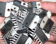
Another common assumption made by everybody including me is that everybody knows that pins in TO220 packages go from left to right when you are looking at the opamp side with the reference printed.
Another common assumption made by everybody including me is that everybody knows that pins in TO220 packages go from left to right when you are looking at the opamp side with the reference printed.
RE: Post # 295
Hi Dan -
This is what I was referring to in my PM to you talking about circuits running together. I didn't know how else to word it , have never seen the 2 types of boards and thought perhaps there was wire impregnated in the one type and you used a soldering iron to 'connect' between points. Now I see it's still basically point to point but difficulty avoiding contact with other eyelets in the one type board.
Am I getting this correctly?
BTW - having a hard time finding source for these boards. Google with terms used only gives you a couple places and both seemingly expensive. I like that board you used was both numbered and lettered.
I'm big on 'anal retentive' and would have preferred the one type board but your point is good, other does seem the better choice.
I also don't like the bare wire connections. Any reason you can't simply use insulated wire and strip ends and solder points?
Same vein of thought. Nick states at D.D. that this is a good time to start using color coding of wires properly as universally understood. Shouldn't we be incorporating this concept here?
If there I missed it ... recommended gauges of wire?
Thanks - Bluto
Bluto said:Great - just realized this should be in with new thread!
Bluto
Well, I just realized that Radio Shack carries three different sizes of veroboard (phenolic--no copper), as well as the e-board. The great big veroboard, at $5, is a pretty good value.
You can use insulated wire if you like. That "bare" wire is actually tinned copper. A nice alternative, inexpensive, and laborious, is the 24ga (or 22ga or 20ga) single conductor economy speaker wire. Its terrible if used for speaker hookup, but it works great for short-distance signal cable. There's also "ribbon" cable with the same single-conductor copper inside. Its not for long runs, but it does quite well at short runs. For the botique, you can get the same stuff with silver solder on it, but don't expect a difference in performance from the price.
Gauges of wire? Just concentrate on making the power star ground (main power ground) thicker/stronger than everything else. The power star ground needs to be "the point of least resistance" and that's why its cable (the 0v and the CT cable) should be thicker than any other wire in the amplifier.
Help again please
Hi,
I finished one channel successfully doing p2p without veroboard. The dc offset was ok and the sound was very good. However I realized that there was a big risk having all those cables and connections flying around, specially since my soldering skills are not very good yet. So I decided to take it all apart and build it again using the same parts and schematics but using a piece of board to make it more stable and safer.
Anyway I finished and when testing the dc offset by putting a 10 ohm resistor as a bridge on the speaker terminals, the resistors burns immediately
(smoke, flames, etc).
I have checked all the connections and seem all right. I wonder if in the process of desoldering and soldering again I may have damaged the caps, resistors or even the chip itself because of excessive heat.
Can I test the chip with a digital multimeter?
Any ideas of what might be happening?
Edit: I might have connected the V+ and V- cables from the bridge to the chip the wrong way around. Is this relevant?.
Many thanks
Antonio
- Status
- This old topic is closed. If you want to reopen this topic, contact a moderator using the "Report Post" button.
- Home
- Amplifiers
- Chip Amps
- Commercial complete Gainclone kit for a beginner?