Hi Nuuk -
Are you Nick? Not trying to be funny though that sounds so, just e-mailed Nick at D.D. a couple of days ago looking for Mark Houston.
As said, I think D.D. likely one of the best regards gainclones and there is tons of info over there.
Gychang and I and I think likely hundreds of lurkers have finally simply gotten the courage to say 'Hey - we don't get it but we want to do it'. It's likely simply an aptitude thing. I got into this DIY Audio over a year ago. One of the 1st things I did was go buy an Electronics Handbook and the Loudspeaker Design Cookbook. Both had been recommended to me as a beginner. 2 days later I was ready to jump off the roof! These are not books for beginners. They assume you have a fairly decent degree of understanding. They are like asking a guy who changes his own spark plugs to rebuild a transmission.
It's not just D.D. ... It's the whole DIY Audio community. Thats not to say there is anything wrong with that either, it's simply set up assuming you have a degree of knowledge or an aptitude in that area.
If you or any of the guys who have built them were here and ' showed' guys like us how to build our 1st one we'd likely get it just like that. Show us a schematic and 4 pictures and 50 terms we have no idea what the meanings of are and we're totally lost.
That was the reason I was looking for Mark here on the forum as his design was one of the simplest I'd seen and it was uncanny that Gychang posted a quest looking for a complete kit with pictures rather than schematics as he was having trouble as well and we'd done so within an hour or so of each other.
If you look at earlier posts you'll see we argue as to who is dumber. He's a Neuerologist and I've been Self employed since 1985 and still have a roof over my head so it must just be we're both dumb regards Audio and schematics.
I think gainclones are coming back due to peoples interest in separates for amplification. Were I you, I'd do a pictorial step by step on your hybrid gainclone/ valve because if I learn this I'm coming back over by you again next. I'd bet money it's the next wave.
Your site is outstanding, this thread is some dummies ( some smart guys too) trying to see if we can come up with a design we understand. The other stuff is over our heads. All help appreciated.
Bluto
Power, Power, and yet more Power. ")
Let's cover transformer lingo for a moment.
EDIT2: Fun photo content in this post.
Our LM3875TF can use dc rails voltages from 25vdc to 37vdc.
For academic reference, its centerline tolerance is approximately 30vdc. EDIT: Figures given are at expected power output levels
Well, the transformer outputs AC.
This is changed into dc by the rectifier (4 diodes or one-piece block).
Transformer lingo.
48vct and 24v dual, are 24 + 24 volts ac (rectifies to 35 +35 dc)
40vct and 20v dual, are 20 + 20 volts ac (rectifies to 30 +30 dc)
36vct and 18v dual, are 18 + 18 volts ac (rectifies to 26 +26 dc)
Dual secondaries, indicates that there are 4 wires for output, and quite confusing. See the power supply forum for that tangle.
Center tap, vct, indicates that there are 3 convenient wires for output, as used with the easy one-piece bridge rectifier.
Applied:
How much power do we get out of LM3875TF. . .
With 8 ohm speakers:
For 30vdc, we get 42 watts
For 35vdc, we get 57 watts**
With 6 ohm speakers:
For 26vdc, we get 39 watts
For 30vdc, we get 52 watts
For 35vdc, we get 71 watts (use big heatsinks)
With 4 ohm speakers**:
For 26vdc, we get 50 watts
For 30vdc, we get 50 watts
**If using the 48vct (or 24+24) transformer, rectified to 35vdc rails, then please purchase generously large heatsinks for your amplifier, as that can provide a measure of safety in case of "accidental" connection to 4 ohm speakers. Builder's tip: If you favor the 4 ohm drivers, then use the cheap inductor for the woofer and "pad" the mid&tweet. Else, choose a lower voltage transformer.
Meanwhile, back to the power. . .
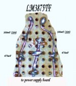
A clear picture:
The above makes a power supply.
Click the picture below for an example of one super-easy method to connect an amplifier board with the pair of 470uF, pair of 0.1uF, and the LM3875TF to the power supply.
Let's cover transformer lingo for a moment.
EDIT2: Fun photo content in this post.
Our LM3875TF can use dc rails voltages from 25vdc to 37vdc.
For academic reference, its centerline tolerance is approximately 30vdc. EDIT: Figures given are at expected power output levels
Well, the transformer outputs AC.
This is changed into dc by the rectifier (4 diodes or one-piece block).
Transformer lingo.
48vct and 24v dual, are 24 + 24 volts ac (rectifies to 35 +35 dc)
40vct and 20v dual, are 20 + 20 volts ac (rectifies to 30 +30 dc)
36vct and 18v dual, are 18 + 18 volts ac (rectifies to 26 +26 dc)
Dual secondaries, indicates that there are 4 wires for output, and quite confusing. See the power supply forum for that tangle.
Center tap, vct, indicates that there are 3 convenient wires for output, as used with the easy one-piece bridge rectifier.
Applied:
How much power do we get out of LM3875TF. . .
With 8 ohm speakers:
For 30vdc, we get 42 watts
For 35vdc, we get 57 watts**
With 6 ohm speakers:
For 26vdc, we get 39 watts
For 30vdc, we get 52 watts
For 35vdc, we get 71 watts (use big heatsinks)
With 4 ohm speakers**:
For 26vdc, we get 50 watts
For 30vdc, we get 50 watts
**If using the 48vct (or 24+24) transformer, rectified to 35vdc rails, then please purchase generously large heatsinks for your amplifier, as that can provide a measure of safety in case of "accidental" connection to 4 ohm speakers. Builder's tip: If you favor the 4 ohm drivers, then use the cheap inductor for the woofer and "pad" the mid&tweet. Else, choose a lower voltage transformer.
Meanwhile, back to the power. . .
A clear picture:
An externally hosted image should be here but it was not working when we last tested it.
An externally hosted image should be here but it was not working when we last tested it.
An externally hosted image should be here but it was not working when we last tested it.
An externally hosted image should be here but it was not working when we last tested it.
An externally hosted image should be here but it was not working when we last tested it.
An externally hosted image should be here but it was not working when we last tested it.
The above makes a power supply.
Click the picture below for an example of one super-easy method to connect an amplifier board with the pair of 470uF, pair of 0.1uF, and the LM3875TF to the power supply.
Attachments
Bluto.
I found this site useful for explaining component functions.
http://www.allaboutcircuits.com/
As I understand DC blocking, a capacitor will allow AC to pass through it but will block DC out. This would apply to C4 in this DD schematic
http://myweb.tiscali.co.uk/nuukspot/decdun/gainclone4.html
If the input source has DC on the output it will make it as far as C4 but that will filter the AC audio signal through to the next stage but stop any DC from going any further.
I hope that helps a bit
John
Bluto said:
I have yet to encounter anywhere a single site that takes you from start to finish on how to build a gainclone pictorially along with written instructions as to what it is you are doing and why you are doing it.
Hi,
You still need to basically know what you are doing before you should attempt to build anything that runs off mains voltage - it's dangerous.
You can't be educated in a day with a few pictures.
danielwritesbac said:
We could manufacture such a site.
Based on the quick assessment that only about 30% of the contributions to this thread so far are either accurate or useful, maybe you should put that thought on the shelf for a while.
If you go ahead, you should preface it with a warning: "most of what will be presented is either conjecture of misinformation, with the occasional tidbit of actual fact."
MJL21193 said:Based on the quick assessment that only about 30% of the contributions to this thread so far are either accurate or useful, maybe you should put that thought on the shelf for a while.
If you go ahead, you should preface it with a warning: "most of what will be presented is either conjecture of misinformation, with the occasional tidbit of actual fact."
Prove it.
I'd be especially fascinated if you posted something helpful and informative.
Re: tube stock...?
You are referring to?
I already have.
Bluto said:.... for heat sinks
You are referring to?
danielwritesbac said:
I'd be especially fascinated if you posted something helpful and informative.
I already have.
John -
Your statement about near to 30% of whats written being factual had me laughing out loud.
Please tell us which 30% if you want to be helpful but of more importance if you actually know the difference tell us where you learned it.
I'm one of the admitted dummies and all I know is what I've learned from reading on this, manufacturers and other sites.
Would you recommend that all the 'Kits' be taken off the market or that proof of a Degree in Electronics be required to purchase one?
Peter Daniels posted to this thread offering to sell one of his Kits to a Man who is a Neurologist that started by asking for such with 'pictures provided'. Are his Kits dangerous?
The Moderator or Owner of another site just stated that He built his 1st kit after much reading ( I've done better than 500 hours on this subject, most of it is redundant, as previously stated, or applies to design modification) and that many have sent him e-mails stating they've built theirs by looking at pictures at his site.
This forum has hundreds of testimonies from Cooks to Truck Drivers claiming to have built their 1st in less than a few hours. Where did they get the knowledge? I see no testimony of anyone getting electrocuted.
I'm not being a smart*ss here, I'd like answers to those questions.
These things aren't SET Amps. Granted there's a danger to anything electric if proper procedure isn't followed but the goals stated are clear - avoid the $100 cost of a kit you might fry by making 1 wrong solder joint. 500 guys on this site built their own because they knew how from somewhere and simply bought the parts separately rather than a kit. Someone showed them, they looked real closely at the pictures that are on the net or they bought a kit with instructions the 1st time out and just bought parts thereafter. They didn't go back to College for 4 years and receive a 'Chip Amp Degree'.
If you can tell me another way they managed it I'm all ears and thats why I'm involved in the thread.
Theirs no rocket science involved in assembling these. You needn't understand theory. You simply need to be shown a decent design and how .
If I'm wrong or those who are participating are wrong you can save us all alot of time.
Thanks - Bluto
Heatsinks:
http://www.alliedelec.com/Search/ProductDetail.asp?SKU=619-0079
and
http://www.apexjr.com/Sinks.htm
Economy source 1: Old SLOT type (very long + big) computer CPU heatsinks can be used. I'm not talking about the little squares, no. These are the big long rectangles, found in outdated computers, and usually cost nothing. The type of CPU found with these heatsinks is the kind "on a card" that plugs in at 90 degrees to the board. EDIT: and these aren't quite large enough in case of using 4 ohm speakers.
Economy source 2: At Salvation Army, Goodwill, Garage Sales, and so forth, you can find broken down old equipment with the likelihood of whopping huge heatsinks inside--just peek through the vents to see.
Personally, I wouldn't salvage classic equipment; no, I'd repair it.
But, any "black box" digital era stuff--well I'd sure recycle that.
Technique: Hot air will go up, if possible. In order for that to happen, a vent underneath the heatsink is needed. That lets in cool air, onto the heatsink. Next, you'll need to let the now-hot air out of the amplifier's enclosure. An additional vent at the top or at the top of the rear panel, will complete the job. That's cool air in at the bottom, and hot air out at the top.
With LM3875TF (black tab, insulated), you can mount the heatsink external to the enclosure.
Materials: Heatsink, thermal compound (computer supply store or electronics hobby supply), and. . .
If you don't have the "TF" (LM3875TF) insulated chip (black tab), then you'll need to add a mica insulator between the chip and heatsink, else the heatsink will be high voltage.
Heatsink size: Simply put, too big costs less than too small.
Bluto said:
I believe, but won't speak for him, that Gychangs quest is to finally make this simple enough that an actual 'newbee' can build one that works.
Greg - Apologies for butting in , still your thread and your decisions , I just got excited about getting something going and a bit frustrated after all I'd read.
Bluto
Bluto said:
Gychang and I and I think likely hundreds of lurkers have finally simply gotten the courage to say 'Hey - we don't get it but we want to do it'. It's likely simply an aptitude thing.
Bluto
Bluto: thanks for speaking out lould. I am in total agreement.
I know nothing on the electronic side. My purpose for starting this thread was for a total newbie to have someone lead us a step-by-step, "solder middle red wire to this black wire" hopefully with a picture. This may be asking too much so I thought of a possibly a beginner's gainclone kit (have managed to build a kit from 41Hz (after 3 tries following their picture layout), but the amp does not enough power and the kit uses tiny buggers SMD) if anyone knew.
I am hopeful this thread remains a Beginners thread for how to build Gainclone for Dummies. I am certainly one of them.
gychang
Re: John Blackburn -
Sure! You're welcome. Hey! Would you like to create the website? I'm much too disorganized to write something like that.
For instance. . .
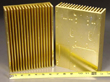
A slight error--I forgot to mention that the APEX Jr. gold heatsinks, go oriented, as any heatsinks do. . . fins vertical. That could make quite the unusually shaped amplifier enclosure However, the Aavid Thermalloy at Allied, is only 6" tall--not an unusual height for an amplifier.
So far, I think we have selected an amplifier chip, got the entire power circuit, and got a heatsink. If anyone is lost, may I recommend http://www.audiosector.com as one of the rare and good examples where applying cash to a problem, can actually work out fine.
Back to our project here. . .
Maybe we should do the NFB (set the gain) next? That's extremely easy, but there are two options.
Bluto said:Thanks -
Took a quick look . Thats some heady stuff but pretty well written. This will help me with some basics I've struggled with as well.
Appreciated - Bluto
Sure! You're welcome. Hey! Would you like to create the website? I'm much too disorganized to write something like that.
For instance. . .
A slight error--I forgot to mention that the APEX Jr. gold heatsinks, go oriented, as any heatsinks do. . . fins vertical. That could make quite the unusually shaped amplifier enclosure
However, the Aavid Thermalloy at Allied, is only 6" tall--not an unusual height for an amplifier. So far, I think we have selected an amplifier chip, got the entire power circuit, and got a heatsink. If anyone is lost, may I recommend http://www.audiosector.com as one of the rare and good examples where applying cash to a problem, can actually work out fine.
Back to our project here. . .
Maybe we should do the NFB (set the gain) next? That's extremely easy, but there are two options.
Gychang - Hi-
Your Welcome.
Where Ya been? I think Dan has about got this thing built in his head and just waiting for your approval.
You have alot of comments to give opinions to. This got crazy real quick.
You approve his design, Dan can build the prototype, I'll write the manual and you take the photos but be careful, people can get electrocuted with those digital cameras! All other newbees benefit.
Only teasing John and I do value you opinion if you see something seriously wrong here or want to tell us how everyone else did all this original stuff in the gallery and lived.
Contribute soon - this is your thread and we want to hear from you.
Bluto
MJL21193 said:Apologies gentlemen, perhaps I was a little harsh in my assessment.
Staying away from the "gray" areas of improved SQ due to miracle component selection and sticking with the recommended schematics will work best.
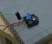
Fully operational LM3886TF amp:
Nice job! Do you have a photo of one on vero or e-board?
Oh, and I'm hoping to avoid the component selection stuff, as much as possible.
Howabout your suggestion on a preamplifier project? That would be great!
Bluto said:. . . but be careful, people can get electrocuted with those digital cameras!
Really? Oh right!! If the flash gets wet, the camera becomes a stun gun (taser). Yes, I remember. I was cycling on oklahoma freewheel tour, it rained, I took a picture. . . OMG!! The capacitor in the camera flash discharged onto my hand.
Electroshock: Its probable that power circuit capacitors will retain a charge even after the gainclone amplifier is unplugged.
Make this "cap drainer" tool:
Materials:
A 50 ohm, 10w sandcast (speaker type) resistor
A pair of test leads (like replacements for ohmmeter/multimeter)
Solder the leads to the resistor and tape that thing up.
After unplugging the amplifier, use the cap drainer (with 50 ohm resistor) tool to drain the capacitors.
Next, measure with your multimeter (set on DC) to see if the item is safe to handle.
Bluto said:you take the photos but be careful, people can get electrocuted with those digital cameras! All other newbees benefit.
Gosh, I didn't know that, I'll have to wear rubber gloves from now on!
MJL21193, exit stage right. Good decision.
Gwad, this is a funny thread.
I have put a few brief GC notes and pictures here over the years that may help or not.
Pay attention to Rod Elliott's P19 and P72. When you buy Rod's PCBs you get access to the BOMs and construction instructions. This is how I started.
http://users.tpg.com.au/gerskine/greg/gainclones.htm
regards
danielwritesbac said:
Howabout your suggestion on a preamplifier project? That would be great!
Well, to be honest, that's one of the first comments I read by you that I didn't agree with. These amps don't need a preamp for most standard sources, just a volume pot.
Addition of a preamp will, in most cases, drive the chip amp into clipping. You need to set the chip amps gain to a minimum of 10 to avoid oscillation, but these handle higher gain easily.
The chip amp .xls (link I originally sent you way back) will set typical gain around 21.
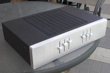
Active LM3886 amp. Six channels for two 3-way speakers. Each chip amp board has it's own active filter for each driver.
Attachments
- Status
- This old topic is closed. If you want to reopen this topic, contact a moderator using the "Report Post" button.
- Home
- Amplifiers
- Chip Amps
- Commercial complete Gainclone kit for a beginner?