I'm a Chinese
This is my amplifier design with LME49810
Green that is used to test the resistance of 8R 1000W
I am not good at English
We look at it
the date on Picture is wrong, I forget to adjustment
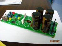
This is my amplifier design with LME49810
Green that is used to test the resistance of 8R 1000W
I am not good at English
We look at it
the date on Picture is wrong, I forget to adjustment
An externally hosted image should be here but it was not working when we last tested it.
An externally hosted image should be here but it was not working when we last tested it.
An externally hosted image should be here but it was not working when we last tested it.
An externally hosted image should be here but it was not working when we last tested it.
An externally hosted image should be here but it was not working when we last tested it.
An externally hosted image should be here but it was not working when we last tested it.
An externally hosted image should be here but it was not working when we last tested it.
An externally hosted image should be here but it was not working when we last tested it.
 Gentlemen, politics are not allowed in DIYaudio
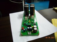
AndrewT said:R28 is on the wrong side of C2+3 for conventional NFB.
So what is it's purpose?
I don't know the intention of the designer, but R28 can help to shift the -3dB cut-off frequency at the low end to a lower value. A spice simulation shows that when equal resistor values are used for R28 en R29, the -3dB frequency at the low end is about halved compared to the situation with R28 omitted and half the value for R29 (i.e in both cases equal gain in the audio frequency range).
My approach would be to use an AC coupling capacitor at the input, and then use equal resistor values for R21 and R29. This will result in minimal DC offset at the output of the amplifier, because the input bias currents will give equal voltage drop over R21 and R29. The voltage gain of the amplifier in the audio range is 1+ (R28//R29)/R23. By selecting low values for R29 en R23 compared to R28, a low capacitor value can be used for C2+C3. This enables the use of a single film capacitor instead of two elco's in series, without compromising the -3dB cut off frequency at the low end of the audio spectrum.
CornelisJ said:
I don't know the intention of the designer, but R28 can help to shift the -3dB cut-off frequency at the low end to a lower value. A spice simulation shows that when equal resistor values are used for R28 en R29, the -3dB frequency at the low end is about halved compared to the situation with R28 omitted and half the value for R29 (i.e in both cases equal gain in the audio frequency range).
My approach would be to use an AC coupling capacitor at the input, and then use equal resistor values for R21 and R29. This will result in minimal DC offset at the output of the amplifier, because the input bias currents will give equal voltage drop over R21 and R29. The voltage gain of the amplifier in the audio range is 1+ (R28//R29)/R23. By selecting low values for R29 en R23 compared to R28, a low capacitor value can be used for C2+C3. This enables the use of a single film capacitor instead of two elco's in series, without compromising the -3dB cut off frequency at the low end of the audio spectrum.
Thank you~!
I am not familiar with English, so it is difficult to explain my own.
I hope you will understand what I said

Re: dont you thing ....
Can use the + -95 V voltage,To a greater power ,this depends on your transformer
sakis said:that 6 outputs to run 100w is a cind of waste ????....unless this all thing is designed to run in higer rail voltage also
Can use the + -95 V voltage,To a greater power ,this depends on your transformer
- Status
- This old topic is closed. If you want to reopen this topic, contact a moderator using the "Report Post" button.
- Home
- Amplifiers
- Chip Amps
- my lme49810 AMP