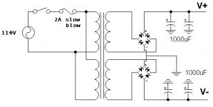
The deal here is that since you have separate "virtual ground lines" from each secondary, you don't get a lot of current flowing back and forth which typically puts noise down the ground line. In short, you actually get control over where you place the ground line. Draw the schematic with one bridge and see what happens (by shorting the two secondaries as a center tap -- the center tap is the ground. Consider how the current will flow back and forth as the diodes switch on and off -- not optimal. Ideally, you don't want current to flow in the ground at all, or at least have control over how this happens which is impossible with 1 bridge.
To make this work, you need to have the secondaries come out of the transformer as shown, but you don't need a split primary. (Thus, a Center Tap transformer will not work, so upgrading old equipment is not always possible)
Petter
To make this work, you need to have the secondaries come out of the transformer as shown, but you don't need a split primary. (Thus, a Center Tap transformer will not work, so upgrading old equipment is not always possible)
Petter
I forgot to put in the downside (which is not huge) which is that you get an extra diode drop. This means more power is lost in the power supply.
Also, you should NEVER use diode bridges for audio (except support circuitry if you have any and want to save some money or space. I have standardized on IRF 15ETH06 from www.irf.com as a reasonable compromize between cost, high voltage operation, soft recovery and general usability for pretty much any circuit. Since I don't build a lot of stuff it is nice to have a small stack of these around. Furthermore this standardization made me come in a good deal cheaper given the volume discount prevalent in electronic part sales (with significant savings kicking at 10 units -- you need 8 for each construction you make, and even 16 for each power amp monoblock if you go all out)
Now, it is quite possible that the Silicon Carbide Schottky units (be prepared to fork out $10 per unit if you can indeed find them) from Infineon may just be the best thing since sliced bread in certain situations and that regular Schottky's or other soft recovery units may give you better still performance depending on your application (Search the forum or go here http://www.diyaudio.com/forums/showthread.php?threadid=3951)
You might also consider snubbers, but the should not be complete necessity with the IRF unit I suggested as one of your alternatives. There is an article in a back issue of Audio Electronics from AudioXpress with the theory of it all (starting with the measurement of actual resonances ...)
Bridge upgrades must be (with CAP upgrades) the best value ever in audio modifications.
Petter
I'm sitting here wondering why I get only +23,2 v and -23,2 v after bridges using a 25+25v toroid in the above circuit. What do I do wrong? Shouldn't I get +35 and -35 volts?
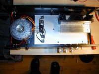
This is going to be a three channel Gainclone amp.
I guess I wired the secondaries from the toroids wrong...?
/Jan
This is going to be a three channel Gainclone amp.
I guess I wired the secondaries from the toroids wrong...?
/Jan
Attachments
Diode bridge VS diodes
First of all, thanks for your reply")
Wh-what ?
Petter, you mean I shouldn't use diode bridges in my power supply ? Could you please explain me why ? I'm quite interested about your point of view.
Regards,
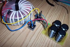
btw, here's my current Power Supply setup
First of all, thanks for your reply
Also, you should NEVER use diode bridges for audio (except support circuitry if you have any and want to save some money or space
Wh-what ?
Petter, you mean I shouldn't use diode bridges in my power supply ? Could you please explain me why ? I'm quite interested about your point of view.
Regards,
btw, here's my current Power Supply setup
Attachments
Elkaid,
don't take Petter too literally, it's more a philosophical statement. Like you should never listen to you CD player unless it has a low jitter clock installed.
A bridge will work just fine. Experiment with soft recovery, snubbers and the whole bowl of wax see what sound you get.
don't take Petter too literally, it's more a philosophical statement. Like you should never listen to you CD player unless it has a low jitter clock installed.
A bridge will work just fine. Experiment with soft recovery, snubbers and the whole bowl of wax see what sound you get.
Elkaid, don't take Petter too literally, it's more a philosophical statement. Like you should never listen to you CD player unless it has a low jitter clock installed.
Ok !
With all those "strange" suggestions to improve sound (such as connecting resistors or speaker cable "backward", etc..
), I'm beginning to doubt about everything that I took for granted concerning electronics. (Is ohm's law still valid ?
 )
)Well, thank you guys !
Diode Bridges
Hi, I think Petter meant ordinary diode bridges.
Soft recovery diode bridges like IXYS VBE17 or Schottky diode bridges assembled from discrete diodes can be used with good results.
www.ixys.com
Hi, I think Petter meant ordinary diode bridges.
Soft recovery diode bridges like IXYS VBE17 or Schottky diode bridges assembled from discrete diodes can be used with good results.
www.ixys.com
I just got up -- so sorry about the wait
Yes, Elso -- you are right about what I meant, and thanks Grataku for the needed adjustment.
Typically diode bridges as building blocks are of poor quality. When you assemble the bridge from superior parts you will in my experience get much better results -- the cost in parts is very low.
Diodes are de-facto non-linear devices that switch on and off resonant ciruits at 100-120Hz in a diode bridge. You would't believe how much high frequency crap they feed into your device (and how much they feed back to the net which typically finds it's way back into other components.
Petter
Something here I'm not sure about:
If one toroid feeds two channels do I need two bridges or four bridges with the above circuit?
I my GC I use six bridges for three channels (see pic), and I guess this is the way it should be. But I'm in doubt now cause I keep blowing my fuses after having unwired all 6 bridges and wired them up again, cause I was unsure on my wiring with those 23 volts DC before caps mentioned before ...
Basic electronics, I know, but electronics is my Achilles Heel...
I don't know if Petter's answer is totally right but not very wrong anyway. One extra thing which isn't mentioned. One bridge results in half wave rectification. What happens if you only take out positive voltage? How do current travel in the windings?Elkaid said:What are the differences between a power supply using 2 rectifier bridge as shown on the schematic versus a power supply using only one ?
Your help is greatly appreciated ! Thanks !
You are a little bit nicer to the transformer (less heat) with two bridges and you creates less overtones towards the mains. I don't know big the difference is though.
The disadvantage with two bridges is losses in a extra recifier brigde, also the extra cost...
Another property of the two bridge configuration is the lower voltage across the diodes (half of the voltage compared to the single bridge configuration). Though I do not know exactly the effect of this...
At least you should take this in consideration while chosing the diodes (max. voltage ratings).
Fedde
At least you should take this in consideration while chosing the diodes (max. voltage ratings).
Fedde
Petter said:
Diodes are de-facto non-linear devices that switch on and off resonant ciruits at 100-120Hz in a diode bridge. You would't believe how much high frequency crap they feed into your device (and how much they feed back to the net which typically finds it's way back into other components.
Petter
Hi,
When I use double bridge rectifier, I putt in count (and possible oscillation/your idea) double number of nonlinear element (diode). When I use single bridge (or 4 diode) my circle of energy flow is shorter, isn't? If we think about GC like minimalist amp, why we complicated with to many diodes? Price here is not only 4 diode more in circuit. Price is posibility of bigger ground loop problems, unstability-oscillation etc. IMO
Regards
Hm, you get more losses in the bridges with two bridges, but as I said earlier the transformer get less losses.fedde said:Another property of the two bridge configuration is the lower voltage across the diodes (half of the voltage compared to the single bridge configuration). Though I do not know exactly the effect of this...
For normal "light duty" I think that it doesn't matter, only more expensive with two bridges...which is nothing compared to the whole cost of an amp.
- Status
- This old topic is closed. If you want to reopen this topic, contact a moderator using the "Report Post" button.
- Home
- Amplifiers
- Chip Amps
- 2 Rectifier bridges : Why ?