Hey all;
I've been reading the forum for a couple of months now and there's certainly a lot of information. In fact I think I've read too much and now I don't know how to start.
I'd acquired an old Realistic receiver and a very old Sansui receiver, both of them are broke; no sound from the Realistic plus the radio doesn't work, and the chips in the sansui are burnt out, (receiver lights up though and tunes, just can't get a signal out, shame cause it's really good looking).
I was thinking about making an LM3875 chip with point-to-point wiring and a separate power supply. Theoretically i was just going to buy the LM3875 chips. and trying and make the rest from scavenged parts. Then I started reading about hum problems when using a point to point and it seems that using a PCB is the easiest way to get good results. I basically want to make something just for the enjoyment of making it and that I can cut my teeth on, I'd like to progress onto a valve pre-amp one day. I'm also intrigued to know if a diy amp can impress me with the sound
So my options are:
1) Stick to my original plan and make a point to point amp with shiny new chips and use the other amps as doners.
2) Buy a PCB and kit and make a good quality amp with a separate scavenged power supply. Why
3) Forget the scavenging and buy all new components.
I currently have a very old Realistic SA-1500 which looks beautiful and sounds very nice, (it was being throw away out in a clear out and I picked it up, the fuse and blown and the power light doesn't work. ) with a pair of old Paradigm SE5 Mk3's. My source is a slimserver music streamer. I don't know much about hi-fi but it all sounds rather good. So I want to try and make an amp to drive the Paradigm's.
Any advice on the best approach to take and any advice on scavenging parts from old equipment. Is it worth using old caps and resistors ?
king regards
I would also add that if you start with Peter Daniel's basic kit, and then use that as a platform to experiment and add better parts as your whim chooses, you'll be able to hear what change gives the best results (resistors, caps, etc), especially if you're starting with a salvaged transformer (though, it should still be a pretty decent transformer). If you start with his best kit, you'll have less to experiment with, and thus it might not be as much fun in the long run.
then again, YMMV
-Jared
then again, YMMV
-Jared
Well, you could take stock of the parts that you already have.
It seems that you already own:
heatsinks
transformers (suitable voltage unknown)
power cord
capacitors
resistors
screws and bolts
knobs
potentiometers
source selector switch
dpdt switches
misc switches
radio and RIIA (functionality unknown)
enclosures (suitability unknown)
And, it seems that you're looking for a baseline.
Peter Daniels AudioSector.com kit comes to mind.
My personal preference would be dual-mono layout, although stereo format (if you have only one transformer) is available
The AudioSector amplifiers, like most quality power amp modules, are designed (voiced) to require a buffer or preamp. That is a good idea (its actually easier and less expensive that way--just believe me). So, it seems that acquiring the power amplifier modules and its matching buffer/preamp, is the next step.
You'll find about the same thing with any chipamp kit or project, with one exception. . . The audiosector kit has extensive support, baselines, examples, and the designer frequently visits this forum where you can also (search feature) find a lot of his writings, replies, and yet more baselines (well-tested).
So, its shopping time.
Like you I thought of wiring point-to-point however it quite easy to make mistake and make a mess of the wiring.
I end up using a chipamp board(on sale), for my LM3886, I don't use the alotted spots(ie on the PCB) for the resistors I wire directly to the pins esp the feed back(22K) resistor ie pins 3 and 9. This applies to other resistors. Use the board you mount the LM3886 on the board and solder the pins to the board. The resistors then rest on the board and all other terminations, eg I/P,O/P and power. The latter is useful us you may want to remove the wiring EASILY, YOU DON'T HAVE TO DESOLDER! YOU GET THE BEST OF BOTH WORLDS.
I mount 4 boards in one case, ie 4 channels. I will post picture soon.
You can get cheap LM3875's PCBs from this site:
http://stores.ebay.com/semielectric
I bought $10 for 2 PCBs recently, LM3875 not LM3886.
cheers.
Fatbob, I favour P2P because you can see where all the connections go (and learn from it), rather than just soldering components into position on a PCB somebody else designed.
If you are confident that you don't have any duff components. by all means use what you have to save cost and reduce your carbon footprint.
If you can stand some more information, may I suggest that you look
here ?
If you are confident that you don't have any duff components. by all means use what you have to save cost and reduce your carbon footprint.
If you can stand some more information, may I suggest that you look
here ?
Fatbob,
please let me point to the obvious.
You like the looks of your receiver. The tuner (and thus the power supply) still works.
Have you thought about simply replacing the broken receiver's amplifier board(s) with chip amps?
Just an idea,
Sebastian.
PS: In order to discuss this further you would of course have to determine what's good and what's bad inside the unit, i.e. where the fault came from and what damage it caused.
All thanks all for the advice;
Still no sure what to do. I'm comfortable with soldering so that doesn't worry me, but I have no idea about good layout, so I would know how to eliminate hum etc. Maybe I'll let fate decide..check I've got exactly the right working parts to follow the point to point method (except for the chips) and build it, or if I haven't got all parts just buy the Peter Daniel's kits ( i was actually looking the Brian Bell kits) and use the transformer and rest of the hardware to finish of.
Maybe I should stop trying to think about all possibilities and just build something. Get me up and running.
sek : - I acquired the receiver from the electrics shop at the University where I work, they'd already tried to fix the power amp and failed. I tried to find the tuner feed so I could tap of that and use it as a tuner coupled with my amp......but it was no avail, ( it's a sansui R30 if anyone can tell me where I can get feed from). Don't know what else to do to try and rescue it. I really like the idea if I could get to the tuner signal. Plus it's one big circuit board, its not separated into separate boards. I'll probably scavenge the realistic first, its a good hefty transformer, giving of +/- 30 V. plus whacking great caps.
thanks for all the advice, most kind of all of you.
regards
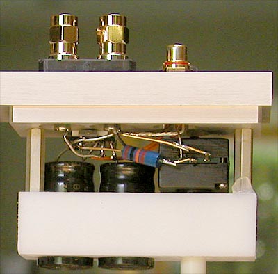
If you already considered p2p, go with it, it's hard to make mistake.
I build some of my amps that way too: http://www.diyaudio.com/forums/showthread.php?s=&threadid=76609&highlight=

I build some of my amps that way too: http://www.diyaudio.com/forums/showthread.php?s=&threadid=76609&highlight=
Maybe I should stop trying to think about all possibilities and just build something. Get me up and running.
My old guru used to say that a woman always does the washing up four times. Three times in her head and once in the sink.
So yes, go for it.
- Status
- This old topic is closed. If you want to reopen this topic, contact a moderator using the "Report Post" button.
- Home
- Amplifiers
- Chip Amps
- Advice on how to start a LM3875 amp project