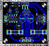
Here are some of the expected comments.
- - Did you read post #30? The rails are reversed.
- Fuses should not be used like that. If only one of them blows, you will get the full DC from the other rail at the output and through your speaker. That can cost you your speaker. Fuses ought to be used in a way that both rails will be interrupted in case of a fault. On top of that the fuse values appear very big and their characteristics are not specified.
- Miter the right angled trace from R2 to C7 or make a straight trace between them.
- Delete the antenna below the In+ terminal.
- Do you really want to use an electrolytic capacitor for Cin?
- Do you know the reason, why Nordic chose R7 with 10 Ohms, while the datasheet proposes 1 Ohm? If you don't, stick to the datasheet.
pacificblue said:Here are some of the expected comments.
- - Did you read post #30? The rails are reversed.
- Fuses should not be used like that. If only one of them blows, you will get the full DC from the other rail at the output and through your speaker. That can cost you your speaker. Fuses ought to be used in a way that both rails will be interrupted in case of a fault. On top of that the fuse values appear very big and their characteristics are not specified.
- Miter the right angled trace from R2 to C7 or make a straight trace between them.
- Delete the antenna below the In+ terminal.
- Do you really want to use an electrolytic capacitor for Cin?
- Do you know the reason, why Nordic chose R7 with 10 Ohms, while the datasheet proposes 1 Ohm? If you don't, stick to the datasheet.
I have red about the rails.
I don't want electrolytic capacitor for Cin.
I asked about this layout cause i didn't want to do p2p. Is there a better layout for this chip that you are aware of?
Thanks for the notes pacificblue.
pacificblue said:. . .
- Do you know the reason, why Nordic chose R7 with 10 Ohms, while the datasheet proposes 1 Ohm? If you don't, stick to the datasheet.[/list]
Speaker zobel is listed at 10R for two reasons:
1). The simple reason that it avoids putting an unnecessary load on a little amplifier.
2). Protect the resistor from burnout.
1R + a polyester or Mylar cap assumes that the high internal resistance in the recommended capacitor is going to contribute some additional resistance. The resistor will not last unless you use 10w capacity.
4R + a polypro or polyester or mylar cap is a working alternative, without making unwarranted assumptions. The resistor will not last unless you use 5w capacity.
10R can use a reasonable size 1w to 3w resistor. And, 10R + 100n Ceramic provides flexibility for solo, for bridged, or for paralleled configurations.
No. Strange as it may seem, most of the promising ones come with fuse holders. As if it were more important to protect a 2 € IC than a much more expensive speaker.zikinho said:Is there a better layout for this chip that you are aware of?
If you specifiy, what exactly you expect, maybe somebody else can point you to an adequate PCB.
- - Do you want to etch yourself one- or two-sided or rather buy a ready-made PCB?
- Do you want a mono or a stereo PCB? Or even multi-channel?
- Would you like to have the rectifiers on board or separate?
- Can you handle SMD components or should everything be through-hole?
- You don't like P2P, but what about perfboard?
pacificblue said:
No. Strange as it may seem, most of the promising ones come with fuse holders. As if it were more important to protect a 2 € IC than a much more expensive speaker.
If you specifiy, what exactly you expect, maybe somebody else can point you to an adequate PCB.
- - Do you want to etch yourself one- or two-sided or rather buy a ready-made PCB?
- Do you want a mono or a stereo PCB? Or even multi-channel?
- Would you like to have the rectifiers on board or separate?
- Can you handle SMD components or should everything be through-hole?
- You don't like P2P, but what about perfboard?
- I want to etch the single sided board myself.
- Mono or Stereo, both would do.
- I have already made a couple of rectifier boards so there is no need for them.
- No SMD, only through-hole.
- Will try perfboard but would like to have etched pcb.
You know, my first experience with SMD was like. . . why is this thing so much smaller than the end of the soldering iron?
However, after having a bit of experience with soldering through hole in very compact layouts, I'd have to say that SMD isn't more difficult to solder, but rather those little things are much easier to misplace.
Some SMD can be quite handy. One ready example is that your entire NFB can fit right to the chip pins. I'm not necessarily endorsing practically zero isolation, but its okay for the typical 22k feedback resistor itself.
zikinho said:I know smd has it's advantages but components are to small for my eyes .
Oh me too!!!
But, my cats spot them instantly.
I do not know the location of their stash.
danielwritesbac said:But, my cats spot them instantly.
I do not know the location of their stash.
Try to put your ear to their stomachs, provided they let you. If you hear hifi-noises, you will have found the stash.
pacificblue said:Try to put your ear to their stomachs, provided they let you. If you hear hifi-noises, you will have found the stash.
He bit me.
Well, this makes me take the ROHS compliance a bit more seriously. I guess that we all have to do that anyway. Its especially good to watch ROHS compliance, because if you find something you like, it might be suddenly discontinued if it wasn't ROHS compliant.
The ROHS compliance is probably good in case your components are mistakenly eaten or inhaled (not recommendable). Yes, those SMD's are just too small.
Nope. The RoHS legislation does not make electronic products safely edible or inhalable.danielwritesbac said:The ROHS compliance is probably good in case your components are mistakenly eaten or inhaled
It actually does not even allow you to eat or inhale products that fall below it. That would be considered improper disposal, and would probably lead to a fine or imprisonment. According to RoHS legislation you are obliged to bring those products to the proper place for proper disposal.
pacificblue said:
Nope. The RoHS legislation does not make electronic products safely edible or inhalable.
It actually does not even allow you to eat or inhale products that fall below it. That would be considered improper disposal, and would probably lead to a fine or imprisonment. According to RoHS legislation you are obliged to bring those products to the proper place for proper disposal.
I take it that this means a lot of favorite stuff has been discontinued without much point to it at all?
Not, if you see it from a long term perspective. RoHS is aimed to reduce hazardous waste and to improve the recycling quota. In the face of an ever increasing amount of electronic products that will all some day become waste, it is one of many necessary steps to prevent this world from becoming something we know from bad science fiction movies.danielwritesbac said:I take it that this means a lot of favorite stuff has been discontinued without much point to it at all?
Multiple 1875
By putting multiple devices in parallel, it is possible to achieve lower die temperatures, thus over long periods of time better reliability.
Also, 1875 is very small…if space is a primary consideration, it might have an edge.
I would love to see a 25 watt @8ohm amp with three 1875 on a board about 3” wide. A pair bridged would give a cool 50 watts in a small, economical package.
This post contains an amazing board/layout.:
http://www.diyaudio.com/forums/showthread.php?postid=1487510#post1487510
pacificblue said:
2 x LM1875 means per deinition 40 unprotected Watts. 1 x 3875 means 56 protected Watts, with the same component count as 1 x LM1875. Output power is similar enough to forget about it, price will be similar, complexity will be higher for 2 x LM1875. The only logical reason left to use 2 x LM1875 instead of 1 x LM3875 is to use it as a learning exercise.
By putting multiple devices in parallel, it is possible to achieve lower die temperatures, thus over long periods of time better reliability.
Also, 1875 is very small…if space is a primary consideration, it might have an edge.
I would love to see a 25 watt @8ohm amp with three 1875 on a board about 3” wide. A pair bridged would give a cool 50 watts in a small, economical package.
This post contains an amazing board/layout.:
http://www.diyaudio.com/forums/showthread.php?postid=1487510#post1487510
Attachments
Hi,
each chipamp will need to be designed for the effective load it sees.
Calculate the required heatsink for each.
Finally add up the heatsinks. Is this smaller or larger than a dual or single chipamp feeding that load.
All this complexity and it could be overcome by going discrete.
each chipamp will need to be designed for the effective load it sees.
Calculate the required heatsink for each.
Finally add up the heatsinks. Is this smaller or larger than a dual or single chipamp feeding that load.
All this complexity and it could be overcome by going discrete.
Re: Multiple 1875
What exactly is the amazing part of it?
That the PCB size is extremely small? And then you need a transformer and big power supply caps, a heatsink and space for connectors, main switch, volume potentiometer, protection circuits, ...
toolsresearch said:This post contains an amazing board/layout.:
http://www.diyaudio.com/forums/showthread.php?postid=1487510#post1487510
What exactly is the amazing part of it?
That the PCB size is extremely small? And then you need a transformer and big power supply caps, a heatsink and space for connectors, main switch, volume potentiometer, protection circuits, ...
Re: Re: Multiple 1875
Yes, despite the ancillaries you mention, which no doubt take up space, as you point out, it is quite small! For that reason, again, obviously, it could be shoehorned into smaller spaces.
Also, what about the lower die temps. with a parallel config.?
No doubt the minimalist camp will object to the ballast resistors; however, I have listened extensively to the Rowland 3886 based integrated with many speakers and it is stunning, ballast resistors and all!
pacificblue said:
What exactly is the amazing part of it?
That the PCB size is extremely small?
Yes, despite the ancillaries you mention, which no doubt take up space, as you point out, it is quite small! For that reason, again, obviously, it could be shoehorned into smaller spaces.
Also, what about the lower die temps. with a parallel config.?
No doubt the minimalist camp will object to the ballast resistors; however, I have listened extensively to the Rowland 3886 based integrated with many speakers and it is stunning, ballast resistors and all!
- Status
- This old topic is closed. If you want to reopen this topic, contact a moderator using the "Report Post" button.
- Home
- Amplifiers
- Chip Amps
- LM1875 PCB, Which To Use

