I've read somewhere about not using linear regs.(1.5A max for LM317&LM337 ) in power amp. They can be used in preamp P.S. though,
or does using it for treble app. reduces the load on linear P.S.? Pls elaborate.
Personally, I'm using +/-21 SMPS for LM1875
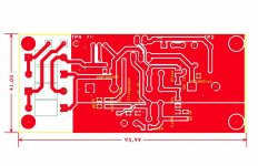
One more thing-what is the dimension of the PCB shown in #246? The design is way better than the one in LM1875 datasheet.
Thanks,
availlyrics.
There exist adjustable linear regulators that can handle 5 Amps, such as LM338, LD1084 (LDO), and others. The LT-1083 LDO type goes to 7.5 Amps.
Also, it is very easy to use two positive linear regulators (i.e. no negative regulator) to make a power supply with both positive and negative outputs.
Bass waves are taller and take a lot more power than mids&treble.I've read somewhere about not using linear regs.(1.5A max for LM317&LM337 ) in power amp. They can be used in preamp P.S. though, or does using it for treble app. reduces the load on linear P.S.? Pls elaborate.
A 1.5A LM317 in combination with 1.5A LM337 is just about more than one LM1875 chip can take anyway (the regs have protection, the amp does not). And, little voice coils in tweeter and midrange drivers wouldn't last but a few minutes with that amp at full blast. Amperes meets thin wire? Well, you'll still need a bit of a crossover to serve as protector.
So the prospect of using the LM317+LM337+LM1875 for mids&treble amp is:
1). Power: There wouldn't be any clipping, and that's not a cheat but rather that the amp is sheer overkill for this job. However, for good stereo separation, bigger prettier sound, we'd like to run LM317+LM337 per Each LM1875 as if pretending to build monoblocs.
2). Tone: The LM1875 run from regs is a fresh sounding thing that is easily malleable for tone. . . much unlike the LM3886 which offers mostly excellent bass and beautiful bari in combination with shouty, super-clear but somewhat unpleasant mids.
3). Protection: Without inbuilt protection of its own, giving an LM1875 the protection in LM317+LM337 is quite useful. And, the LM1875 can have capacitive output when driving mids&treble crossover, which can block DC accidents thoroughly.
For low cost, simply regulate the LM1875 mids&treble amp down to 26vdc+26vdc rails from your 35vdc+35vdc LM3886 bass amp's power supply. Using some passive crossover components for the woofer will help inspire good bass without incessant audible clipping from the LM3886 bass amp.
The LM1875 mids&treble amp can have a very tiny input and output cap to accomplish most of the bass roll-off; however, a midrange and tweeter pair should probably be worked out with good driver matching and a first order series crossover (whatever isn't used by midrange is sent to tweeter and vice-versa) to redirect rather than slag signal. If a voltage divider is used in passive mids&treble crossover, you'll want to attach an additional series capacitor to whichever tweeter terminal doesn't have a crossover (the additional roll-off helps tweeter survive high power use). It would be interesting to see if the LM1875 mids&treble amp can keep up with an LM3886 BPA300. Quadruple power from the bass amp means that the mids&treble amp must output 6db more to keep up. It probably can.

Personally, instead of an "active speaker" eq system, I much prefer a "powered speaker" which does have some passive crossover components. Anyway, "powered speaker" lets you use whatever is needed to match up the speaker as nicely as possible with its amplifiers.
Last edited:
Yes. LM1875 QK50, K50 is a readily available kit.
The NFB cap is too small and the feedback resistor is too high, but the PCB works just fine.
Those Nanya 220uF caps are new old stock, so don't hit 'em with maximum power right away--refresh them with a 9v~12v dc plug pack first (and then drain the caps after), and wear goggles the first time any older capacitors are powered up.
K50 specific mods:
Replace the kit's 22u NFB cap with 220u
Add either 0.47u (or smaller) electrolytic and/or 22n (or smaller) polyester cap, in parallel with and underneath the NFB cap.
Replace the 180k feedback resistor with 75k
Replace the 10k feedback shunt resistor with 2.2k
Replace the 1k tone damper with 470 ohms
LM1875 specific protection:
Fuses are good, but not enough protection and not convenient for daily replacement. We will want to protect both the chips and the fuses.
Monobloc (and dual-mono) provides a decent answer for controlling current--One transformer and one power board per Each LM1875. To power a pair of LM1875, you'd need a pair of transformers of not more than 2 amperes apiece. Momentary power for bass peaks comes from the power supply boards.
One pair of these: Antek - AN-0518 to power dual-mono LM1875.
And perhaps a pair of something like this:
Attachments
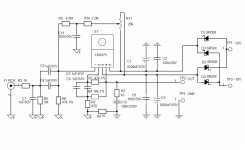
I am confused by the lack of a Centre Tap from the transformer.
Is this a single secondary rated at 18Vac?
The schematic shows a Power Ground symbol and shows both supply rails connected to the Power Ground via smoothing capacitors.
The schematic also shows a Bias Voltage from the supply rails to the +ve input to set the chipamp to halfway between the supplies.
Is this a single secondary rated at 18Vac?
The schematic shows a Power Ground symbol and shows both supply rails connected to the Power Ground via smoothing capacitors.
The schematic also shows a Bias Voltage from the supply rails to the +ve input to set the chipamp to halfway between the supplies.
thank youI get the gain from input to output as approx. 25.2db or 18.1 numerically, fractionally higher if you discount the attenuating effect of the input filter.
1k and 1nF give a cutoff frequency of 159kHz.
The LF response of that circuit is extremely restricted by the way (C5/6).
how I can change low frequency response - is there need to increase C5/C6 ?
p.s. R9 R10 R11 C11 are not used
I am confused by the lack of a Centre Tap from the transformer.
Is this a single secondary rated at 18Vac?
The schematic shows a Power Ground symbol and shows both supply rails connected to the Power Ground via smoothing capacitors.
The schematic also shows a Bias Voltage from the supply rails to the +ve input to set the chipamp to halfway between the supplies.
the transformer have 18 0 -18 and 18 0 -18 for the other channel
i have been listening to this amp for some years but this tread has very good explanations about the values of he elements in the circuit, so I decided to try some experiments to see if there will be some noticeable change
the pcb is for smd elements and some of the capacitor are with leads with spacing 5mm(for C3, C4, C5, C6), so if I want 33uf I have use electrolyticC5/6 should be increased to a combined value of 33uF. That would give a -3db point somewhere around 4Hz (currently around 30Hz)
capacitor - how I have to place the negative terminal to leg 2 or the other way
Attachments
Its not really possible to do that. The feedback network has two parts to it in this design, the 47k for the feedback needed to maintain the DC conditions, and then the additional 10k and 470 ohm to finalise the gain. That second part has to be AC coupled.
You would have to ask the designer why they chose to do it this way, and not follow the more conventional route.
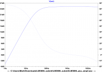
The best way to see the effect of changing values is to simulate the circuit. You can do that using a basic opamp configured with your parts wrapped around it.
There are on-line tools for determining simple R/C filter cutoff frequencies but non that would allow calculation for a set up like this.
Search for 'R C filter calculator' and you will find many examples.
You would have to ask the designer why they chose to do it this way, and not follow the more conventional route.
The best way to see the effect of changing values is to simulate the circuit. You can do that using a basic opamp configured with your parts wrapped around it.
There are on-line tools for determining simple R/C filter cutoff frequencies but non that would allow calculation for a set up like this.
Search for 'R C filter calculator' and you will find many examples.
I would avoid "making" a nonpolar electolytic.
OTOH, buying a "real" nonpolar (bi-polar) electrolytic like fe. Nichicon Muse would work nice.
( www.nichicon.co.jp/english/products/pdfs/e-es.pdf )
There are also other makers, of course, so personally I would choose a real (not "homebrew") bi-polar electrolytic.
OTOH, buying a "real" nonpolar (bi-polar) electrolytic like fe. Nichicon Muse would work nice.
( www.nichicon.co.jp/english/products/pdfs/e-es.pdf )
There are also other makers, of course, so personally I would choose a real (not "homebrew") bi-polar electrolytic.
- Status
- This old topic is closed. If you want to reopen this topic, contact a moderator using the "Report Post" button.
- Home
- Amplifiers
- Chip Amps
- LM1875 PCB, Which To Use