sneih said:some opinion that i heard about disadvantage of using fuse after rectifier /board is can damage your expensive speaker if only 1 of 2 fuse death...
maybe someone can explain how it do that?
The first amplification stages in the IC are usually referenced rail-to-rail. If one rail is missing their output is biased to the remaining rail and pulls the following stages towards that voltage. The result depends on which rail is missing and is either DC at the output (may blow speakers) or a blown IC, which usually means DC at the output afterwards (again blowing speakers).
With two rectifier bridges (one per rail) you can run into the same issue with fuses before the rectifiers. Use either a correctly dimensioned fuse before the transformer or a detection circuit that reacts to a missing rail by switching the other one off as well.
Thanks PacificBlue!!
I think that two potentially recommendable spots for fuses is:
In series with the mains power switch to the amplifier
In series with the output + of the amplifier (3a fast blo?)
Probably convenient to install these in insulated fuse holders, to the amplifier enclosure, and so they're accessible.
What do you think of it?
From the protective point of view fuses at the amplifier outlet are a cheap and efficient protection for amplifier and speaker alike.
Some people are convinced to hear a difference in sonic performance, when they swap automatic circuit breakers for gold- or silver-plated pure-copper-melting-wire fuses in their home's distribution box. Imagine, how they would suffer with a fuse added between amplifier and speaker.
Which arises an interesting question. Do audiophile melting fuses need burn-in?
Remember there are additional contact points with all their negative side effects, like contact impedance, parasitic capacity and inductivity. Fuse holders are often made from cheap spring-steel, which is magnetic, and the fuse is also a conductor with unwanted side-effects and must therefore have a "sound". For audiophilists these are all arguments against fuses in the signal path.
I once had a pair of speakers with melting fuses to protect the tweeters. I still have some with PTCs for tweeter protection. No significant sonic degradation for me, but then everybody percieves such effects differently.
Hi Folks,
I'm very new on this forum, yes it's my first post!
Following this topic for quite a while now.
I'm working on a LM1875 board to and i see that there are quite a few modifications to do as i read this topic.
My first pcb of the Lm1875 mono power amp.
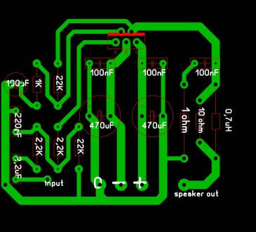
Comments are welcome!
But i want to use two LM1875 parallel per channel. but is that as simple as the word says it is or do i have to change a lot of things?
And how about bridging the chip? The only thing i know that it can't run under 8 ohms load then.
Thanx
I'm very new on this forum, yes it's my first post!
Following this topic for quite a while now.
I'm working on a LM1875 board to and i see that there are quite a few modifications to do as i read this topic.
My first pcb of the Lm1875 mono power amp.
Comments are welcome!
But i want to use two LM1875 parallel per channel. but is that as simple as the word says it is or do i have to change a lot of things?
And how about bridging the chip? The only thing i know that it can't run under 8 ohms load then.
Thanx
Its a very interesting board. Kudos!
Your speaker output zobel (RC) is too strong of a load. Use 8R in order to ensure compatibility with parallel operation. See National Semiconductor's AN1192.pdf for more information about parallel amplifiers.
And, LM1875's inbuilt limiter will reduce current handling to half power when bridged unless supplemented with added output transistors. I'd love to see this in action!
The TDA2050 is pin compatible and will bridge. Use lower voltage.
Wherever Daniel got the idea about the Zobel, it is usually good to stick with the datasheet recommendations, which is 1 Ohm and 220 nF. And use only one Zobel for a parallel application.
LM1875 can be bridged and paralleled. The current will not be halved. It is 4 A peak, the same as in TDA2040. TDA2050 has 5 A peak.
An easier and more logical way to achieve more output power is to select a different IC. Instead of bridging or paralleling LM1875, buy LM3875. Keeps component count low, layout simple and the price will not be much different either.
pacificblue said:Wherever Daniel got the idea about the Zobel, it is usually good to stick with the datasheet recommendations, which is 1 Ohm and 220 nF. And use only one Zobel for a parallel application.
LM1875 can be bridged and paralleled. The current will not be halved. It is 4 A peak, the same as in TDA2040. TDA2050 has 5 A peak.
An easier and more logical way to achieve more output power is to select a different IC. Instead of bridging or paralleling LM1875, buy LM3875. Keeps component count low, layout simple and the price will not be much different either.
I should have said that bridged will not increase the potential for power output with 8 ohm speakers. See, that's a nice bland statement.
")
Zobel? 1R may be a wasteful amount of added load for an amplifier with limited resources, and does not represent a well done RC unless that cap is a 100v (or less) polyester/mylar type typically having 7+ ESR during the audio band. The type wasn't specified and its better not to guess.
There is a minor difference between LM1875 and LM3875 output power at end result (the speaker). It is less than 3db. LM3875 has the spike system that further limits output, plus LM3875 distortion increases with frequency, and so useful power output differences can be slim.
Thanx for the reactions!
I've read the application hints form the technical documentation of the Lm1875 once again.
I've changed several things
The inducter changed to 5uH as the documentation says it should be.
The coupling cap is changed to 220nF polypropyleen 5%. Also following the documentation. Al other caps are polypropyleen 1%.
The input of the pcb is going to be replaced futher to the left. The ducumentation says you otherwise get distortions beqause of the currents from the power supply. Also the speaker output with components is going to be replaced a little bit to the right.
Since i don't care about the size of the pcb I can change everything with hopfully the best results.
maybe a copper plate at c angle on the pcb grounded between supply and input section?
Power supply cables should be twisted I thougt it only has to be done with AC wires and not with DC wires.
Wow the chip can reach 170 degrees before thermal shutdown.
Time to draw a new pcb with a parralel or bridge mode.
I've read the application hints form the technical documentation of the Lm1875 once again.
I've changed several things
The inducter changed to 5uH as the documentation says it should be.
The coupling cap is changed to 220nF polypropyleen 5%. Also following the documentation. Al other caps are polypropyleen 1%.
The input of the pcb is going to be replaced futher to the left. The ducumentation says you otherwise get distortions beqause of the currents from the power supply. Also the speaker output with components is going to be replaced a little bit to the right.
Since i don't care about the size of the pcb I can change everything with hopfully the best results.
maybe a copper plate at c angle on the pcb grounded between supply and input section?
Power supply cables should be twisted
I thougt it only has to be done with AC wires and not with DC wires.Wow
the chip can reach 170 degrees before thermal shutdown.Time to draw a new pcb with a parralel or bridge mode.
danielwritesbac said:There is a minor difference between LM1875 and LM3875 output power at end result (the speaker). It is less than 3db. LM3875 has the spike system that further limits output, plus LM3875 distortion increases with frequency, and so useful power output differences can be slim.
Which is as true the other way round. 2 x LM1875 means per deinition 40 unprotected Watts. 1 x 3875 means 56 protected Watts, with the same component count as 1 x LM1875. Output power is similar enough to forget about it, price will be similar, complexity will be higher for 2 x LM1875. The only logical reason left to use 2 x LM1875 instead of 1 x LM3875 is to use it as a learning exercise.
pacificblue said:
Which is as true the other way round. 2 x LM1875 means per deinition 40 unprotected Watts. 1 x 3875 means 56 protected Watts, with the same component count as 1 x LM1875. Output power is similar enough to forget about it, price will be similar, complexity will be higher for 2 x LM1875. The only logical reason left to use 2 x LM1875 instead of 1 x LM3875 is to use it as a learning exercise.
Yes, of course a parallel LM3875 is worthy of exploration as well.
gekkehenk said:. . .
I've changed several things
The inducter changed to 5uH as the documentation says it should be.
The coupling cap is changed to 220nF polypropyleen 5%. Also following the documentation. Al other caps are polypropyleen 1%.
. . .
Most application guides that contain a speaker output zobel and specify the cap, also specify mylar/polyester/MKT.
These are available with either the appearance of a "box" or as a "dip cap" (looks like bubble) cap. It is the polyester film dip cap that is most specific for speaker output zobel.
Screwdrivers! Oh what an adventure that was.
First, solder a cap, then. . .
2 oz vodka
5 oz orange juice
Next, solder the other cap, then. . .
2 oz vodka
5 oz orange juice
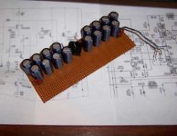
Wow, pretty soon, I had some sort of artsy sculpture sort of power circuit with eighteen caps. This wasn't my best idea.
First, solder a cap, then. . .
2 oz vodka
5 oz orange juice
Next, solder the other cap, then. . .
2 oz vodka
5 oz orange juice
Wow, pretty soon, I had some sort of artsy sculpture sort of power circuit with eighteen caps. This wasn't my best idea.
danielwritesbac said:First, solder a cap, then. . .
2 oz vodka
5 oz orange juice
Next, solder the other cap, then. . .
2 oz vodka
5 oz orange juice
Finally the secret behind many of your posts is revealed.
Merry Christmas
David
pacificblue said:
Finally the secret behind many of your posts is revealed.
Merry Christmas
David
Merry Christmas to you too!
I finally found that thing! It actually has 20 caps (four are snubcaps). Without further delay, here's the not-recommended, too many screwdrivers = too many caps power supply:
Attachments
I,m a big step futher with my pcb design now!!
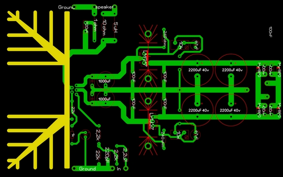
I've build a variable regulated power supply with a LM317 and LM337.
4x 2200uF Nichicon PS series caps. Low esr and impedance.
2x 1000uF Nichicon PS series caps. Low esr and impedance.
Vishay 1837 series 100nF 1% MKP filtering caps.
The output coupling cap is an 220nF 5% Polyester.
At the input is a 2,2uF evox-rifa polyester coupling cap 5%
All resistors are 1% metal films.
The diodes are the Mur-860.
The layout is made by the document of the LM1875.
-The whole print is "euro" sized zo it will fit easy in many housings from 5cm or higher.
- Input and output is as far away as possible from the power supply rails for minimal distortion.
- The ground for the input and output is not connected with the ground from the power supply.
- The ground wire from the transformer is in center point of the rails between the big caps and the voltage regulators.
- Power supply is futher off the Lm1875 for minimal distortion.
The only problem are the voltage regulaters. I didn't know that they could not deliver 1,5 amps at high voltages....oops . So i'm going to use a buffer transistor for both sides?
I,ve looked for other 3amps voltage regulaters, positive and negative but i couldn't vind any pairs. The only one i could find as best match was the LT1083 with the LT350 form Linear.
Does anyone know a better combination with minimal components?
Waiting for comments
Thanx!
I've build a variable regulated power supply with a LM317 and LM337.
4x 2200uF Nichicon PS series caps. Low esr and impedance.
2x 1000uF Nichicon PS series caps. Low esr and impedance.
Vishay 1837 series 100nF 1% MKP filtering caps.
The output coupling cap is an 220nF 5% Polyester.
At the input is a 2,2uF evox-rifa polyester coupling cap 5%
All resistors are 1% metal films.
The diodes are the Mur-860.
The layout is made by the document of the LM1875.
-The whole print is "euro" sized zo it will fit easy in many housings from 5cm or higher.
- Input and output is as far away as possible from the power supply rails for minimal distortion.
- The ground for the input and output is not connected with the ground from the power supply.
- The ground wire from the transformer is in center point of the rails between the big caps and the voltage regulators.
- Power supply is futher off the Lm1875 for minimal distortion.
The only problem are the voltage regulaters. I didn't know that they could not deliver 1,5 amps at high voltages....oops
. So i'm going to use a buffer transistor for both sides?I,ve looked for other 3amps voltage regulaters, positive and negative but i couldn't vind any pairs. The only one i could find as best match was the LT1083 with the LT350 form Linear.
Does anyone know a better combination with minimal components?
Waiting for comments
Thanx!
zikinho said:Any experience with the PSU voltage regarding the sound? With what kind of rail voltage did you get the best sound?
P.S. Merry Christmas everyone.
No, I haven't built it yet so I really don't know. I was planning to use a rail voltage from 28 to 30 volts.
Greetings
- Status
- This old topic is closed. If you want to reopen this topic, contact a moderator using the "Report Post" button.
- Home
- Amplifiers
- Chip Amps
- LM1875 PCB, Which To Use