danielwritesbac said:
OMG! I just got quoted by a guru. I'm smiling like the cheshire cat.
Wow. Thanks man!
P.S. It seems that the computer software that Nordic used, had partially obscured the polarity markings for V+ and V- power inlet terminals, which is what led to the error. This could have happened to anyone if using that software. This reminds me. I need to go buy a new automatic pencil.
Hi Daniel,
You must be confusing me with someone else.
BTW: There is nothing wrong with Eagle, the error is a human error not software. Either the LM1875 component is made incorrectly or the schematic was drawn wrong. This highlights a important point, people should always post the schematic as well as the generated PCB.
regards
sneih said:^
thx for this information!!
btw that is my first homemade 1875. . .
Pretty job there!!!
schematic post 97
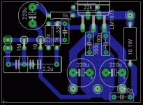
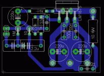
c2 =22uF ( C7 on the PCB) is far too small.
It must be bigger than or equal to 1.4 * C1 * R2 / R3. i.e if C1=2u2F, r2=22k and R3=1k, thenC2>=68uF. Use 100uF. If you want deep extended and phase coherent bass then increase this to either 150uF or 220uF.
If you use an electrolytic then protect it by adding a diode across the cap pins to prevent reverse DC destroying the cap.
AndrewT said:c2 =22uF ( C7 on the PCB) is far too small.
It must be bigger than or equal to 1.4 * C1 * R2 / R3. i.e if C1=2u2F, r2=22k and R3=1k, thenC2>=68uF. Use 100uF. if you want deep extended and phase coherent bass then increase this to either 150uF or 220uF.
So, I take it that the textbook values in the range of 45uF to 100uF (center 68uF) are actually -3db where we'd like flat response instead, so we need to double the capacitor size to get our bass?
no,
if we require flat down to 20Hz, then the amp should have a frequency response a full decade below the flat frequency requirement, i.e. 2Hz F-3dB (RC input filter >=80mS). This will give F-1dB ~ 4Hz which is the most common minimum standard for power amps. I prefer to go slightly lower than that. Pre-amps should go at least an octave below the power amp passband.
I see other designers of repute suggest we go even lower, F-3dB @ 0.6Hz, but I have not experimented that low.
Re: schematic post 97
btw just a few minutes it's sounding hehe
the schematic like this?

what dioda can i used?
thx
thanks daniel!!danielwritesbac said:
Pretty job there!!!
btw just a few minutes it's sounding hehe
AndrewT said:
If you use an electrolytic then protect it by adding a diode across the cap pins to prevent reverse DC destroying the cap.
the schematic like this?

what dioda can i used?
thx
Re: schematic post 97
update:
c7= 68-100uF:
AndrewT said:c2 =22uF ( C7 on the PCB) is far too small.
It must be bigger than or equal to 1.4 * C1 * R2 / R3. i.e if C1=2u2F, r2=22k and R3=1k, thenC2>=68uF. Use 100uF. If you want deep extended and phase coherent bass then increase this to either 150uF or 220uF.
If you use an electrolytic then protect it by adding a diode across the cap pins to prevent reverse DC destroying the cap.
update:
c7= 68-100uF:
An externally hosted image should be here but it was not working when we last tested it.
A couple of notes.
You can update the photo to show 68uF-100uF
You can eliminate the "Out -" trace because 220uF power caps aren't large enough to deal with return AC from the speaker. Therefore the speaker ground should be located at the 0v output terminal of the power supply board in the completed amplifier. That (a single groundpoint for speakers) will also help if you decided to add a headphone jack to the project.
sneih said:ok bro, i will update as soon as possible.
btw can i replace 220uF with any bigger caps?
for the better sounds?
thx
But, this isn't what I was talking about.
Actually, I was talking about the place to ground the speaker.
The speaker ground is actually "speaker return" because almost all of the force that's sent to the speaker does come back into the amplifier, and we don't want that accidentally getting into either of the amplifier's inputs--so don't put speaker return ("out -") on the amplifier board.
You also get better bass if you provide the strongest possible reference to support the speaker's signal, and the strongest reference is the 0v (ground) output terminal of the power supply board. See also "Power Star Ground"
sneih said:ok bro, i will update as soon as possible.
btw can i replace 220uF with any bigger caps?
for the better sounds?
thx
The optimal size will depend on which chip is in use, and many other factors, as well.
Good options include 220uF or 470uF.
Use whatever sounds clearest and use whatever power circuit doesn't promote ringing bass.
Pin compatible chips include:
National Semiconductor LM1875 > Use LM1875.pdf
or
SGS Thompson, ST, TDA2050 > Use TDA2050.pdf
Clone LM1875* > Use TDA2050.pdf
*The clone LM1875 does not differ from the clone TDA2050 except for the label.
Recently, I got the embarassing opportunity to learn more about this issue.
No speaker was harmed, but it was a near-miss. I thought it was a wonderful sale price; however, what I received wasn't what I had intended to purchase. There was more power and more bass, all of inferior quality.
Solution:
Whenever power output per voltage used is out of spec for LM1875.pdf, then use this (TDA2050.pdf):
http://www.datasheetcatalog.org/datasheet/stmicroelectronics/1461.pdf
1). Don't exceed 26.7vdc rails (abs max for clone chip), and please consider using lesser voltage.
2). The optimal components for use at the amplifier board may be different when the chip is a different model.
3). And, keep the "NFB cap" (don't omit), because speaker safety is a primary concern for the less-durable chips.
i just update new layout, maybe like this?
An externally hosted image should be here but it was not working when we last tested it.
- Status
- This old topic is closed. If you want to reopen this topic, contact a moderator using the "Report Post" button.
- Home
- Amplifiers
- Chip Amps
- LM1875 PCB, Which To Use

