Paswa said:
daniel, please explain it a litle or draw or edit my attached pcb image to show me the solution.. I can't figure it out
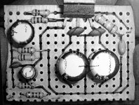
Well, I can't figure it out either, but, here's a guess:
EDIT: This I made so that you can listen to the amp before you order PCBs. The design is comptable with plain vero (phenolic) and experimenters board, which has pads like this: http://www.futurlec.com/Pictures/EXPBRD.jpg so you try different components without getting "tangled" up.
Attachments
Iván Francisco said:Can I drive a pair of tweeters with your design, in a triamp project, without a dc protection circuit?
Thanks
Ivan, most of the designs at this thread have the extra 2 caps on the left side. One decouples the NFB and the other decouples the Input. That is DC protection already.
Its a slight hassle on component selection for those two parts, but a small collection of suitable candidates (for those two parts) can resolve that in a short timeframe. Its especially easy on a triamp speaker project.
The design pictured above can handle 28v rails (good diodes with a 36v center tap transfo).
That amp mates with 6" (almost xmax) to 8" woofers fairly well. It also does, midranges, tweeters, and the lot.
I forgot to mention a couple of things:
The 22k fb resistor goes under the board, it can be surface weld, the same with the 100n decoupling caps (near the chip).
Question: the 22u cap "must" be non polarized? voltage:16V good enough?
Dimentions: width 33mm, deep 25mm
PS: sorry my language guys, you know where I leave.
The 22k fb resistor goes under the board, it can be surface weld, the same with the 100n decoupling caps (near the chip).
Question: the 22u cap "must" be non polarized? voltage:16V good enough?
Dimentions: width 33mm, deep 25mm
PS: sorry my language guys, you know where I leave.
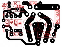
Iván Francisco said:This is the layout to make a home made pcb, is quit good?
It looks nice.
I see two possible problems.
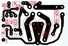
The load that is driven that drives the chip is 22k. Its not hooked up that way. Maybe an SMD will fit horizontally?
Ah! Here goes.
The input circuit goes:
Source/preamp (pass),
potentiometor or 22k (load),
1k (pass),
1m (load),
1uF (pass),
22k (load)
LM1875 (pass)
You can exchange the positions if the 1uF or 1k if you have a preamplifier.
---------------
Next up, a small technicality. The input filter cap, marked square, means poly. That's fine, but 2.2uF might pass more bass than the 22uF cap in the NFB, and you don't want it to do that.
Here's some options.
a) Input, 4.7uF electrolytic--NFB 22uF
b) Input, 1uF poly--NFB 22uF
c) Input, 2.2uF poly--NFB 47uF
Any one of those will have the input filter cap pass less bass than the NFB, which is what you want it to do.
See the attached spreadsheet for reference. Dial in LM1876 because its calculations will be quite similar to LM1875.
Attachments
Iván Francisco said:Question: the 22u cap "must" be non polarized? voltage:16V good enough?
The NFB cap can be polarized. All of mine are.
----------
Here's your gain settings for NFB:
Gain for preamp, 22k vs 1k,
Gain for line level source, 33k vs 1k,
Gain for computer source, 40k vs 1k,
Gain for headphone level source, 44k, vs 1k,
*Its possible to increase the values in proportion (to each other) for a difference in sound, yet at the same gain setting. The spreadsheet above can calculate that.
----------
On the 16v cap question, well, that "seems" a bit small to me. The above examples will deliver only a small voltage into that cap. However, you may wish to interview a variety of capacitors.
Most of my personal preferences for this component have been 100v caps, because I have used whatever sounds nicest to me.
Different brands can give you variety; however, different voltage ratings of the same brand can also give you variety.
I think it takes a comparison of a small collection of samples, for best results.
Iván Francisco said:voltage:16V good enough?
The LM1875 can operate on DC voltages from 8v to 30v (abs max 32.5v); however, normal operation is 25vdc rails.
Normal:
Normal voltages for LM1875 are given by the common and inexpensive 36vct (18+18) transformer. You need at least 36va for each LM1875. At this voltage, that's 1 amper (minimum) for each LM1875. At the low price, monobloc format (+dynamics) is cost effective.
After power supply and rectifier, you get average 26vdc rails.
Expected speaker output power is 28 watts.
EDIT2: The higher voltages are workable for 22 watts in 16 ohm speakers.
EDIT: If at 16vdc rails, LM1875 produces 10 watts for 8 ohm speakers or 15 watts for 4 ohm speakers. So you decide.
I'm going to limit the gain on my units quite a bit to stay within the clean THD band. a gain of about 16 to a 1V signal looks about right, judgeing from the graphs etc.
I have enough high power stuff here, as welll as the usual low power gear like PC speakers... which is what I want to use mine for. I noticed once that my logitech speakers actualy can sound pretty good coupled to a decent amp...
It gets sad when you have too many amps...
I have enough high power stuff here, as welll as the usual low power gear like PC speakers... which is what I want to use mine for. I noticed once that my logitech speakers actualy can sound pretty good coupled to a decent amp...
It gets sad when you have too many amps...
Hi Daniel:
Thanks for your remarks, I'll try for the 1uF poly-22uF NFB.
The spreadsheet you attach is too complicate to my knowledge (my electronycs knowledge is very, very basic, sorry, but I'll try, I promise).
Have 22uF/63V, seems to be ok.
The PS I choose is 18+18V center tapped to drive 4 LM1875 10ABridge diodes is fine? (i.e. KBU10M? and 20000uF/50v per rail?). With this configurtion I expect to drive 2x 5"mid's and 2 tweeters, all 8ohm.
The source I'll use is active crossover from
http://www.siliconchip.com.au/cms/A_30278/article.html
Thanks again.
Iván
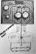
Nordic said:A little further along in concept now.
These will make some nifty multi channel bricks...
Size about 9.5" x 1.8"
Seeing that pretty picture, I can't help but think: "Parallel, parallel, pant, pant, pant, purr, slobber, bark!" or something like that. Hmm. I may have just made the oddest reference yet to AN1192.
Anyway, is parallel an option with that board?Iván Francisco said:Hi Daniel:
Thanks for your remarks, I'll try for the 1uF poly-22uF NFB.
The spreadsheet you attach is too complicate to my knowledge (my electronycs knowledge is very, very basic, sorry, but I'll try, I promise).
Have 22uF/63V, seems to be ok.
The PS I choose is 18+18V center tapped to drive 4 LM1875 10ABridge diodes is fine? (i.e. KBU10M? and 20000uF/50v per rail?). With this configurtion I expect to drive 2x 5"mid's and 2 tweeters, all 8ohm.
The source I'll use is active crossover from
http://www.siliconchip.com.au/cms/A_30278/article.html
Thanks again.
Iván
Hi Ivan!
My electronic knowledge is also basic; however, my soldering and stubbornness are in excellent condition.
Check out the PDF files at national semiconductor. The lm1875.pdf and lm1876.pdf are quite informative. The spreadsheet works from the variables in lm1876.pdf. It is 2x, LM1875's internally, removes monoblock potential, limits power, and adds spike protector's possible noises; however, the data file is a useful reference because it is more up to date.
I can't answer most of your power supply question because I don't know the amperage or VA for your transformer, and also can't imagine why a triamp system would use a quad amp that almost defeats the purpose, instead of monoblocs which are more suited to the goals of triamp systems.
As far as bridge rectifier units, I only have experience with KBPC, which is quite huge. You might ask Nordic and Ashok about the model code for the mini rectifier.
Here's my guess on your PCB layout. I have made the first component at the chip's input to be a load. The input circuit is now driving a 22k load.
Attachments
Hi Daniel:
A'll check all the data you propose, thanks for encourage me to keep learning about this littles (electronycs) secrets.
I also have a pair of KBPC 25A bridge rectifiers. Just wondering to use only one trafo and one PS for the four units.
Thanks a lot for the pcb correction. I'll make the changes immediately.
Cheers,
Iván
Hi Ivan!
On your tri-amp, there's two benefits:
One is that its a crossover style that gives an easier time with driver selection.
The other benefit is great dynamics. To me, that means monoblocs. Otherwise, opportunity is lost.
Although, I can't really answer this for you, here's a guess.
That's mid and tweet for left on one power supply, but mid and tweet for right on the other power supply.
Per each pair LM1875 chips, 70va (2 ampers) and 8800uF (4400uF per rail) is about the minimum. That would also need a pair of 100nF at the rectifier.
See, it doesn't cost more.
Seperate power supplies for left and right, might preserve the intended dynamics of the tri-amp. This is also true of stereo and multi-channel setups, as far as I know.
Hi Daniel:
You are right, I was a little confused about the PS's , one for the right channel and the other for the left channel (both driven one tweeter and one mid's).
I have the caps and the diodes, only need to buy the two trafos.
Thanks again.
PS: tomorrow I"ll post the new pcb's picture.
You are right, I was a little confused about the PS's , one for the right channel and the other for the left channel (both driven one tweeter and one mid's).
I have the caps and the diodes, only need to buy the two trafos.
Thanks again.
PS: tomorrow I"ll post the new pcb's picture.
Iván Francisco said:I have the caps and the diodes. . .
Hi Ivan!
My studies of power supplies do suggest that the 1 piece bridge rectifier unit may be especially helpful to amplifiers running from center tap transformers. I suppose that's because the diodes within are perfectly matched?
In the study, fidelity wasn't measured because there are work-arounds in power supply design, but the measure was heat at the heatsink.
In testing several seperate diodes verses several random 1 piece bridge rectifier units, with transformers pushed over their amperage limits, all of the 1 piece did well, while only one of the diodes did well--the Motorola Litespeed series MR.
The remaining seperate diodes did poorly, and the very worst was On-Semi's MUR860, followed closely by their MR and FR series. That indicates some variance by brand as well as the usual advertisments <> applications.
So, it seems that the 1 piece bridge rectifier unit is a good partner for LM1875. Does anyone have some news on specific models that they currently use?
That would be greatly appreciated. P.S. So far, we have documented KPBC2504, which is huge, so it would be great to have news of some smaller options.
- Status
- This old topic is closed. If you want to reopen this topic, contact a moderator using the "Report Post" button.
- Home
- Amplifiers
- Chip Amps
- LM1875 PCB, Which To Use