Generally the resistor value choosen for the Boucherot cell seems to be 2.7R here at diyaudio.com. Why is that? Wikipedia claims that the values often is in the range of 5R to 10R.
Is there anyway to calculate this value? I guess there is but how important is it? Would a 2.5R do the job as well as 2.7R?
Is there anyway to calculate this value? I guess there is but how important is it? Would a 2.5R do the job as well as 2.7R?
If the amplifier document mentions the name Boucherot Cell, then I'd have to guess you're making a TDA7294 based amplifier? From practical application, those seem to appreciate 4 ohms or larger values because that chip will automatically step down the output power in presence of a stronger load.
There is a great debate about the resistor value. The value of 2.7R was published in National Semiconductor documents for their Overture amplifiers.
Some believe that the value is a mistake, some believe its audibly harmful to sonics, but I beleve that the intention was for large scale production to use an extremely economical polyester capacitor's typical very high ESR (internal resistance) in addition to that 2.7 ohm resistor.
There is, however, no guarantees on satisfactory audio results with 2.7 ohm resistors in amplifier speaker output zobels.
That's because the average ESR approach doesn't indicate any reliable figure during a specific bandwidth (like your upper treble that may get brutalized because the appropriate amount of additional resistance did not occur at that specific bandwidth), so however you look at it, 2.7R (and smaller values) could be a blunder.
One sure-fire solution is to measure the DCR (reference load) of your current speakers. For instance, 8 ohm speakers probably resist DC at 6 ohms. You can use that as a resistor value along with polypropylene (MKP) capacitors that are currently in style. Thus, the wikipedia value of 5 ohms is very close to generally good.")
Capacitor values include 0.22uF, 0.1uF, and 0.047uF. Given that one wishes to avoid impact on the audio band, I believe that the decision on the capacitor value can be done by ear (an excellent detector in the audio band).
Bridged amplifiers need special treatment. This needs two zobels, and each at "half strength," twice the resistor value with half the capacitor value--when two amplifiers are bridged, according to ST Thompson. Maybe I errored in the description? Anyway, the sum total of the two should be the same value as a normal single zobel. I have no documentation for parallel amplifiers.
There is a great debate about the resistor value. The value of 2.7R was published in National Semiconductor documents for their Overture amplifiers.
Some believe that the value is a mistake, some believe its audibly harmful to sonics, but I beleve that the intention was for large scale production to use an extremely economical polyester capacitor's typical very high ESR (internal resistance) in addition to that 2.7 ohm resistor.
There is, however, no guarantees on satisfactory audio results with 2.7 ohm resistors in amplifier speaker output zobels.
That's because the average ESR approach doesn't indicate any reliable figure during a specific bandwidth (like your upper treble that may get brutalized because the appropriate amount of additional resistance did not occur at that specific bandwidth), so however you look at it, 2.7R (and smaller values) could be a blunder.
One sure-fire solution is to measure the DCR (reference load) of your current speakers. For instance, 8 ohm speakers probably resist DC at 6 ohms. You can use that as a resistor value along with polypropylene (MKP) capacitors that are currently in style. Thus, the wikipedia value of 5 ohms is very close to generally good.
Capacitor values include 0.22uF, 0.1uF, and 0.047uF. Given that one wishes to avoid impact on the audio band, I believe that the decision on the capacitor value can be done by ear (an excellent detector in the audio band).
Bridged amplifiers need special treatment. This needs two zobels, and each at "half strength," twice the resistor value with half the capacitor value--when two amplifiers are bridged, according to ST Thompson. Maybe I errored in the description? Anyway, the sum total of the two should be the same value as a normal single zobel. I have no documentation for parallel amplifiers.
The technical reason for this network is to frequency compensate the output stage and even more in combination with a capacitive load. The values are not particulary sensitive but the main thing is to let the output have a resistive load of some decent value and 2.7 - 10 ohms seems reasonable. 2.5 ohms may also be OK. have you read the application note An-1192?
http://www.national.com/appinfo/audio/files/Overture_Design_Guide13.xls
http://www.national.com/appinfo/audio/files/Using_Overture_Design_Guide.pdf
http://www.national.com/an/AN/AN-1192.pdf
http://www.national.com/ds.cgi/LM/LM3886.pdf
http://www.national.com/appinfo/audio/files/Overture_Design_Guide13.xls
http://www.national.com/appinfo/audio/files/Using_Overture_Design_Guide.pdf
http://www.national.com/an/AN/AN-1192.pdf
http://www.national.com/ds.cgi/LM/LM3886.pdf
Thank you for your answers.
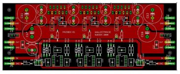
Danielwritesbac: No it's not a TDA-based amp. It's a LM3886-based board with 3 LM3886 in parallel. PA150-config with DC-servo, see attached image. Boards are ordered and I attend to use them in a bridged/parallel configuration. The main reason why I asked is that I discovered that the resistors I wanted to use dont come in the value of 2.7R. Then I started thinking about why that value seems to be the generall choosen one in all configuration I have seen here, since I have read different suggestions at Wikipedia for example.
Your detailed answer has answer my thoughts. People here dont really know why they put 2.7R, they just do it because everyone else do it
Peranders: Yes I have read AN-1192. National only mention this under the partlist for the PA100-schematic, as a "Snubber Network on Output" on page 16. I cant find any other detailed information about it. It's also in the Overture Design Guide but no detailed axplenation about it in there to.
Attachments
I read an application note somewhere about this and how you calculate but unfortunately, don't remember where.CJ900RR said:
Peranders: Yes I have read AN-1192. National only mention this under the partlist for the PA100-schematic, as a "Snubber Network on Output" on page 16. I cant find any other detailed information about it. It's also in the Overture Design Guide but no detailed axplenation about it in there to.

CJ900RR said:Thank you for your answers.
Danielwritesbac: No it's not a TDA-based amp. It's a LM3886-based board with 3 LM3886 in parallel. PA150-config with DC-servo, see attached image. Boards are ordered and I attend to use them in a bridged/parallel configuration. The main reason why I asked is that I discovered that the resistors I wanted to use dont come in the value of 2.7R. Then I started thinking about why that value seems to be the generall choosen one in all configuration I have seen here, since I have read different suggestions at Wikipedia for example.
Your detailed answer has answer my thoughts. People here dont really know why they put 2.7R, they just do it because everyone else do it
Peranders: Yes I have read AN-1192. National only mention this under the partlist for the PA100-schematic, as a "Snubber Network on Output" on page 16. I cant find any other detailed information about it. It's also in the Overture Design Guide but no detailed axplenation about it in there to.
Well, this has all gone completely over my head, so I'll defer to AndrewT on the subject. He is the one who suggested to me that I should avoid violating the reference load of the amplifier no matter if it is a zobel or speaker.
This, I confirmed; however. . . for LM3886, it will not affect the power output, but could turn the resistor brown (LM1875 certainly does) or make the already loud midrange "seem" even more intense because a too-strong zobel could limit the upper treble (applies to LM3886). Perhaps your BP application has a nicer, more open, frequency density than a solo chip. I'd sure like to know.
The resistors you wanted? The zobel component will be most useful if its resistor is sturdy and metal, so that it may reach to and shunt away RF. Just remember that this is a non-audio shunting component, which, being a zobel, is a masking component as well. Its just that the part you "want" is likely to have the opposite effect on sound if used in a shunt role.
I think you just need 1 watt minimum capacity and metal; however, its brand and visual styling won't matter.
As for the rest, and as for the exact figures, I'm stepping out of the way before I step into. . . something unoptimized.
This output RC does several things:
1) together with the open-loop Rout of the amplifier it forms a pole and a zero in the open-loop gain, which, if choosen properly, reduce risk of feedback loop instability with capacitive load. Wrong values increase instability, though.
2) it compensates/damps oscillation tendencies of capacitively loaded emitter followers.
3) with quasi-comp. outputs (the bottom of the LM3886 etc is a NPN-Power transistor in a CFP hookup) it damps the tendency of oscillation of the CFP output.
2) and 3) are the more important parasitic effects, 1) is a control loop theory thing which is more or less insignificant when the snubber R >> Rout (that is, the pole and the zero are too close), which is quite often the case. Therefore the best values are normally found empirically.
4) It can be "misused" to linearize/flatten the speaker impedance at HF. This should better be done after a series L//R and right at the speaker (where it could be dimensioned to approach cable HF impedance to terminate it, which is of importance with high bandwidth amp -- not chip-amp territory, typically)
The cap isolates DC/LF current and is normally choosen to kick in just above the audio range (but still it must be capacitive at HF, which is actually more important), while the resistor is the part that "does the work", and it must be a low inductance type and also wired with low inductance, btw preferably directly to the neg. supply (which must be bypassed also directly to the pos. supply, or alternatively split up the snubber cap in a center tapped cap between the supplies).
- Klaus
According to Philips (Mullard) in their book Transistor Audio and Radio Circuits (1969) the purpose of a Zobel (Bucherot) network is to modify the load on an amplifier so that it appears totally resistive. So reducing any voltage spikes and current spikes on the output transistors.
A Zobel network is a capacitor Cz and a resistor Rz in series placed in parallel with the load of an amplifier.
The values of Cz & Rz are calculated as follows.
If the Loudspeaker is considered equivalent to a series resistance Rs in series with an inductance Ls then:
Rz = Rs
and Cz = Ls/(Rs*Rs)
When these conditions are satisfied then the parallel connection of the Zobel network and the Loudspeaker will present a purely
resistive load to the amplifier. In practice this is of course only an approximation as no correction is made for stray capacitance or lead impedances and a loudspeaker is not exactly an inductance in series with a resistor but the analogy is sufficient to reduce the loading on the output transistors.
The values of Ls and Rs can be found from the Thiele-Small parameters of the loudspeaker.
The Mullard book also claimed better breakdown performance as the amp sees a more resistive load.
KSTR's point 3 The bottom half of the quasi output has a PNP inverter which in the early days of monolithic amps had a lousy frequency response and the amp would go unstable, so the output RC was a convenient way to slug the high frequency response and provide stability. The higher the resistor can be and the lower the capacitor is a sign that the amp has a good PNP response. For discrete amps with better PNPs the RC is typically 10ohm and 0.1uF
KSTR's point 3 The bottom half of the quasi output has a PNP inverter which in the early days of monolithic amps had a lousy frequency response and the amp would go unstable, so the output RC was a convenient way to slug the high frequency response and provide stability. The higher the resistor can be and the lower the capacitor is a sign that the amp has a good PNP response. For discrete amps with better PNPs the RC is typically 10ohm and 0.1uF
My apologies for reviving this old thread.The cap isolates DC/LF current and is normally choosen to kick in just above the audio range (but still it must be capacitive at HF, which is actually more important), while the resistor is the part that "does the work", and it must be a low inductance type and also wired with low inductance, btw preferably directly to the neg. supply (which must be bypassed also directly to the pos. supply, or alternatively split up the snubber cap in a center tapped cap between the supplies).
- Klaus
I am rather curious about the pros and cons of returning zobel load to the negative supply. Most give a standard config by retuning zobel to ground, or rather the center tap, but could it be more beneficial to return the load to the negative rail?
A Boucherot cell is used to terminate a transmission line with a defined impedance to reduce or avoid reflections that interfere with the original signal. That is obviously not the purpose of this RC combination.
A Zobel network is used to linearise an impedance. The only impedance you could linearise at the amp output would be the speaker, but obviously you would need to know which speaker gets connected to find the right values, the values of that RC combination are too small for any speaker, and a well designed impedance linearisation would consist of an additional inductor in series, too. So that is apparently not the purpose of the RC combination either.
That RC combination is simply an RF snubber. The capacitor shorts RF to ground, and the resistor is the current limiter that makes sure the amp does not work into a clean short at high frequencies, where the capacitor's impedance is nearly zero. That is why the National datasheet calls them neither Cbo and Rbo nor Czo and Rzo, but Csn and Rsn.
A more typical value for that resistor is 10 Ohm. The reason to use a smaller value is to make the capacitor more effective at shunting RF to ground at the cost of increasing the frequency where the snubber becomes effective. Drawback is that an amp reproducing corespondingly high frequencies could be driven into its current limit. E.g. an amp that oscillates in the relevant frequency range would certainly suffer even more with 2,7 Ohm than with the usual 10 Ohm. So if the sound of your amp deteriorates due to that resistor, that is an indication of oscillations.
The 100 nF capacitor has an impedance of ~80 Ohms at 20 kHz and ~80 kOhms at 20 Hz. What difference can it make, whether the series resistor to that is 2,7 or 5 or 10 Ohms when it comes to sound quality?
Last edited:
Only with single supply, where the negative rail is usually at the same time the ground.Most give a standard config by retuning zobel to ground, or rather the center tap, but could it be more beneficial to return the load to the negative rail?
That RC combination is simply an RF snubber. The capacitor shorts RF to
ground, and the resistor is the current limiter that makes sure the amp
does not work into a clean short at high frequencies, where the
capacitor's impedance is nearly zero. That is why the National
datasheet calls them neither Cbo and Rbo nor Czo and Rzo, but Csn and
Rsn.
A more typical value for that resistor is 10 Ohm. The reason to use a
smaller value is to make the capacitor more effective at shunting RF to
ground at the cost of increasing the frequency where the snubber
becomes effective. Drawback is that an amp reproducing corespondingly
high frequencies could be driven into its current limit. E.g. an amp
that oscillates in the relevant frequency range would certainly suffer
even more with 2,7 Ohm than with the usual 10 Ohm. So if the sound of
your amp deteriorates due to that resistor, that is an indication of
oscillations.
The 100 nF capacitor has an impedance of ~80 Ohms at 20 kHz and ~80
kOhms at 20 Hz. What difference can it make, whether the series
resistor to that is 2,7 or 5 or 10 Ohms when it comes to sound quality?
Welldone! Well Explained! Superb! Marvelous! Thank you very much! Years confusion has gone in minutes, forever. Thanks a lot.
If you want to partially shunt HF *away* from the chip then those RC dampers should return to GND. Better yet, don't allow HF to get in by symmetrically filtering it at the output terminals.
If you want to control and stabilize the open-loop gain at HF by moderately loading it down then it should return to GND.
Finally, if you want to damp an output section that is prone to parasitic oscillations on its own then the damper should be located close and should return to the appropriate supply pin (neg rail, typically). Taking it to GND is a tolarable detour.
Quite often, we will want all three effects at the same time.
Since GND and the rails must all be shorted together for HF right at the chip it doesn't matter much which route you take.
Last edited:
The 100 nF capacitor has an impedance of ~80 Ohms at 20 kHz and ~80 kOhms at 20 Hz. What difference can it make, whether the series resistor to that is 2,7 or 5 or 10 Ohms when it comes to sound quality?
Thanks, that cleared my doubts!
i might be mistaking here, but if one would be to liearise a speaker's impedance, then it would be done just like if it was part of a crossover.
But the RC zobel can only deal with the rising impedance character of the voicecoil.
But, would not deal with the peak at FS.
Even so, if one adds a zobel to deal with the rising impedance due to voiceciol inductance,
and add a nother compensation network to get rid of the impedance peak, it would still only be able to compenase for a single driver.
Supposedly an active crossover setup (1 driver, 1 amplifier) could benefit from this, as the amplifier would see a close to resistive load. In otherwords it would be easy to drive it, as current spikes would be reduced.
But i think for passive crossover systems this would be verry component extensive to do, and probably would end up pretty bad will all that stuff connected.
Allso i would question if it would lead to any audible effect.
Prehaps a realy general zobel is just to more or less deal with rising impedance characteristics at HF side, and in that case having verry accurate component values are not mission critical.
BTW, one would need an impedance plot of the actual speaker used, be it a single speaker, or one with multiple drivers and a crossover.. witch would add even more complexity to begin with.
Passive Crossover Network Design
This excellent artice shows how to design the compensation networks for a speaker, to make it seem like a resistive load for a passive crossover. Same can be applyd to make the driver seem like a resistive load for a poweramplifier.
Each Speaker Zobel you add, reduces the speaker efficiency.
Because the added parallel impedance draws more current from the amplifier and this added current draw bypasses the speaker.
The other is that within the passband of each speaker, the efficiency of the driver matches the impedance of the voil coil/magnet. The driver outputs a nearly constant SPL for all supplied voltage when fed from near zero source impedance.
Put a high source impedance amplifier (or an added resistor) in as the feed and the high impedance regions of the driver frequency range and you find big "holes" in the frequency response. You don't want that. Adding a Zobel does a similar thing, if there is any source impedance.
- Status
- This old topic is closed. If you want to reopen this topic, contact a moderator using the "Report Post" button.
- Home
- Amplifiers
- Chip Amps
- Boucherot cell (Zobel network) values