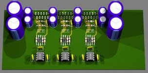
Was just wondering if anyone had tried these pcb's:
http://cgi.ebay.com/Audio-Amplifier...photoQQcmdZViewItemQQ_trksidZp1742.m153.l1262
I'm looking to build something similar to a bpa 300 and was wondering if I could use these since they're inverting.
http://cgi.ebay.com/Audio-Amplifier...photoQQcmdZViewItemQQ_trksidZp1742.m153.l1262
I'm looking to build something similar to a bpa 300 and was wondering if I could use these since they're inverting.
Looks like it follows Nationals standard circuit, should sound "normal". Would not recommend them for a BPA300 design cause they dont have any output resistors, no zobel network and no DC-circuit. They would most likely oscillate (spelling?), overheat and burn if paralleled.
Im working on a pair of boards, not finnished yet. Might order in a week or so.
Im working on a pair of boards, not finnished yet. Might order in a week or so.
Attachments
yeah, i knew about the output resistors, was going to add them externally. I'm new to this stuff, though and didn't know about the other stuff. I actually originally started out just going to build a simple amp, but then I got this great deal on a dual center tapped 1000va transformer, and I got some killer older 12" Kenwoods to drive now. Figured I needed to ramp it up a bit.
Gainclone PCBs
I am hoping some of you may be able to help. I am new to Gainclones and electronics.
Does any one know if I can buy the Chipamp.com or Audiosector.com PCBs in the UK? It would be easier to follow one of these kits.
I am really keen to make my own PCBs if someone has a simple yet reliable PCB design I could use.
I have purchased some copper boards and intend using the photo glossy paper method.
Which size toroidal transformer will give me the greatest flexibility with future upgrades? I have seen some at http://www.airlinktransformers.com/toroidal-transformers.asp
Which amp configuration will best suit my these speakers?
B&W DM601 S2
Crossover is at 4 kHz, efficiency is rated at 88dB/1W/1m, Impedance is said to be 8 Ohms nominal, 4.3 Ohms minimum
Response 70Hz-20kHz +/- 3dB on axis
Harmonic distortion below 1% 88-20.000 Hz at 90dB SPL at 1m.
Power handling is said to be 25-100W continuous of unclipped programme into 8 Ohms nominal
I really appreciate your help.
Ok, so here's a question. I already have a couple of Peter Daniel's boards. If I got some more of those and used the Zobel option, and then added the output resistors externally, would that prevent the oscillation? I may not go for the full 300, I was thinking more of only using 4 chips per channel.
coldfuzion76 said:Ok, so here's a question. I already have a couple of Peter Daniel's boards. If I got some more of those and used the Zobel option, and then added the output resistors externally, would that prevent the oscillation? I may not go for the full 300, I was thinking more of only using 4 chips per channel.
Yes, you can use the inductor externally -- it (or the Zobel) should be close to the LM3875 or LM3886.
Use a 1/2 dowel as a form to wind 10 turns of #18 magnet wire as the inductor -- you can even use RS PVC insulated wire -- slip a 10 ohm resistor through the coil -- this will lower the coil's "Q" dramatically
CJ900RR said:... dont have any output resistors, no zobel network and no DC-circuit. They would most likely oscillate... if paralleled.
\
What do you mean by "DC-circuit" ?
I'm reading the National literature, trying to understand this, but they don't mention any DC circuit.
vectorplane said:
What do you mean by "DC-circuit" ?
I'm reading the National literature, trying to understand this, but they don't mention any DC circuit.
Sorry, my bad. I should have written "servo circuit" witch is the correct name for it. Instead of using cap's to minimize DC-offset, you can use OP-amps to keep it low. Look at Nationals AN-1192 (http://www.national.com/an/AN/AN-1192.pdf) at page 13.
coldfuzion76 said:Was just wondering if anyone had tried these pcb's:
http://cgi.ebay.com/Audio-Amplifier...photoQQcmdZViewItemQQ_trksidZp1742.m153.l1262
I'm looking to build something similar to a bpa 300 and was wondering if I could use these since they're inverting.
I purchased thats pcb's,
i found the pin 8 (IN -) of the 3875 is connected straightaway to ground.
Is a joke to resolve it, but in fact the pcb is not working.
CJ900RR said:
Sorry, my bad. I should have written "servo circuit" witch is the correct name for it. Instead of using cap's to minimize DC-offset, you can use OP-amps to keep it low.
Oh, a servo circuit. I see
I know about the National paper on using multiple chips, but this is a single-chip amp.
I've bought boards from Peter Daniel, and Chip-Amp before, but I don't know if they have this "servo amp" on them.
I'll have to check when I get home.
I'll have to check to see if they have the Zobel as well.
Cheers
I have both now, and they don't include the servo, but they do have the zobel. I bought 6 of BrianGT's boards to use in my amp, and I have a quick question, Would I want to use the zobel on every board or just connect one single one after the resistors on the output? I'm going to use 3 per channel.
Sorry to be an idiot.
Help me understand this:
If you parallel 3 amps per channel, is it because you want to drive loads lower than 4 ohms?
Or you just want a wider margin of safety?
Or do the chip amps have better THD performance if you keep each one working at a lower current level?
Help me understand this:
If you parallel 3 amps per channel, is it because you want to drive loads lower than 4 ohms?
Or you just want a wider margin of safety?
Or do the chip amps have better THD performance if you keep each one working at a lower current level?
- Status
- This old topic is closed. If you want to reopen this topic, contact a moderator using the "Report Post" button.
- Home
- Amplifiers
- Chip Amps
- chipamp pcb?