I have been toying with the idea of building a compact, moderately powered amp for my "work" computer that would be capable of driving a small bookshelf speakers. This has to be compact due to office space limitations, and it won't need to crank out much power since high volumes will be right out of the equation.
Enter the obvious choice: LM1875's driven by a +24V or +48 wall wart. (And before anyone suggests, I am indeed considering a +/-24, but I am not sure if it will fit in the case I have in mind)
I was originally considering buying one of Peter Daniel's USB DAC's for the front end of this project, but after thinking what I really needed, the size of Peter's unit (and the fact that it was too good for my needs--sorry Peter!) lead me to try and put together a one shot solution that integrated the USB DAC and amplifiers into one board to effectively minimize space.
I have attached the first rough draft of the circuit I am thinking of using for this project. It is essentially duct taping Russ White's PCM2707 USB circuit used in his Opus project in front of a couple of LM1875's using a single ended PSU as per the National data sheet. So far there has been zero optimization of the circuit, and I know there will be some cleaning up between the digital out and the opamp input, but I wanted to get the idea out there in case anyone has any brilliant ideas.
In the mean time, I do have a couple of questions if anyone could offer up some suggestions:
1) What crystal would you recommend for use with the 2707? I sort of got lost in that section of my Digikey catalog and figured someone here would offer up some quick suggestions. Russ?
2) I know the LM3886 and LM3875's work great with unregulated PSUs. How about the LM1875s?
Like I said, if anyone has any brilliant ideas, I would love to hear them.
(Edit: Attached the schematic--that would help!)
Attachments
If you want something compact, you might want to look into class D.
Particularly something like this: http://cgi.ebay.ca/2-8W-8ohm-4ohm-M...ryZ39783QQssPageNameZWDVWQQrdZ1QQcmdZViewItem
Or this:
http://cgi.ebay.ca/2-15-watt-4ohm-T...ameZWDVWQQrdZ1QQcmdZViewItem#ebayphotohosting
You won't have to worry about heat, which is a very nice bonus.
Particularly something like this: http://cgi.ebay.ca/2-8W-8ohm-4ohm-M...ryZ39783QQssPageNameZWDVWQQrdZ1QQcmdZViewItem
Or this:
http://cgi.ebay.ca/2-15-watt-4ohm-T...ameZWDVWQQrdZ1QQcmdZViewItem#ebayphotohosting
You won't have to worry about heat, which is a very nice bonus.
Touche'TheMG said:If you want something compact, you might want to look into class D.
That just isn't in the cards this time around, but I really do like the idea! Thanks for the suggestion. For now I am sticking with the opamps, but if a second generation comes around I may have to look into that.
David
I will absolutely be making boards for this. I typically make prototype boards at home, but I will be posting board layouts for anyone who wants them. If the prototype works OK, I will be happy to look into doing a group buy if there is enough interest.ttan98 said:Are you making PCBs for thses combo? I am interested in buying the PCB.
David
Here's the update. After thinking it over and looking at what wall warts are available, and re-reading the "popping" problems associated with power up and power down, for single ended PSU's with the 1876, I decided to go with a more traditional +/- supply. I'll be using a BCB mounted transformer, and if my back of the envelope math is correct, I should be able to shoe-horn everything on the 10 X 7 cm board with minimal effort.
I have to decide on a transformer, and then I'll start laying out the boards.
David
I have to decide on a transformer, and then I'll start laying out the boards.
David
Attachments
Watching with keen interest. I've built up an Alien which uses a PCM2702, and I know you're some way down the road, but the 2702 has excellent sound, is pretty simple to build in the form of the Alien, and is a well-supported design. It specs out quite a bit higher than the 2707, and is SSOP28 which may be easier to manually solder in.
I'm looking at almost exactly the same thing, but I've decided to integrate a couple of things together at the construction level as I don't have the expertise for board creation. I have a couple of LM4766 spare, and I've built those P2P before, and a spare Alien or two. This will run off an inbuilt supply, and power a couple of minimonitors which I'm still dawdling on.
All the best. I like these tiny and quick projects!
Edit: I just noticed your output configuration, and the PCM series is happiest when driving >10K loads - your current config is about 1.5K. The 2707 can handle the load, but performance may be better if the 3.3K resistors are changed to 33K-47K range.
Edit2: Also a typical ECS 12MHz has a load capacitance of 33pf, or at least that's what came with the Aliens. I'm not sure they'll operate properly with a 1uF cap.
Edit 3: The PCM 2702 does not require the output pop/zobel filter. However all these solutions will pop somewhat, so an amp with a built-in mute will help supress the switch-on and switch-off pops with a well-designed mute circuit.
Edit 4: The one big advantage of the 2707 over the 2702 is that you can implement volume control directly on the chip, but you aren't using it...
sangram,
Many thanks for the suggestions!
1) I wasn't aware, but I haven't thought about those values much yet. I am looking at changing both those and the gain resistor values to make sure everything is optimized to get the most out of the system, so those values are quite likely to change. Thanks for pointing out the preferred load of the 2707, though!
2) The caps were just place holders while I looked for appropriate crystals. I know the total capacitance around the xtal should be 33pF. Those values will change once I decide on a crystal. If you have specific suggestions, I would love to hear!
3) I'm not really interested in including a mute function for this amp, thus tying the mute pins to ground to keep the amp on all of the time. It is my understanding based on the specs of the LM1876 that the internal circuitry should suppress turn on/off pop pretty well this way as long as there isn't a voltage on the inputs. I'll play with the prototype and see if this needs to be changed.
4) I completely agree that the volume control pins are nice, but I was originally designing this amp to be used from a computer front end. I hadn't considered "on amp" controls since I would have a full control panel on the desktop. I can easily include headers for these pins, though, to allow future use of these pins. The more I think about it, the more I like this suggestion!
Thanks again!
David
I double checked the data sheet to make sure I didn't miss anything after I first replied to your post, and the output of the 2707 is configured to drive a pair of headphones! Since the data sheet recommends loads greater than 32 ohms, I am rather happy with the 1.5K load presently in the circuit. Fortunately, this can be changed rather easily once the boards are built if need be!sangram said:Edit: I just noticed your output configuration, and the PCM series is happiest when driving >10K loads - your current config is about 1.5K. The 2707 can handle the load, but performance may be better if the 3.3K resistors are changed to 33K-47K range.
Still, thanks for making note of this since I wanted to double check those values anyway.
David
EDIT: Woopsie! I finally found the part of the document you were taking about! The noise characteristics, etc. are indeed best driving a load greater than 10K. I stand corrected!
The Allied Electric store brand 36vct (18+18vac) center tap EI core transformer, is very tiny, super strong (rated 1 amper and gladly does 4), and its #227-2060. Its Canadian made, very polite, and its pretty. Of course, that makes sense. ")
Still, that voltage makes for big heatsinks for LM1875's or about a third larger (whopping big) for an LM1876.
The Parts Express "China Special" transformer has proven itself to be decent at audio amplifiers, its $3 and its a 2 amper 25vct (12.5+12.5vac). This won't play as loud because of the lower voltage, but it will decrease your heatsink size requirements. This low of a voltage may cause unsatisfactory results with LM1876 due to the noises during transients that it can make when undervolted. However, LM1875's will do just fine because LM1875's are "soft clip" amps, unlike the rest of the Overture chips.
These are very small EI core transformers, but "known good" for the application. I believe that the 36vct takes 6800uF per rail while the 25vct can get by on 4400uF per rail--minimums.
For space saving, you can prevent power supply issues without going through all the hoops if you buy 4 (instead of 2) of whatever cap you're using for the NFB protection cap. These are usually things like Mallory SK, Nichicon KZ, Elna Tonerex, etc. . . usually in values around 22uF to 47uF.
Just get an extra pair.
Now, if this additional pair (1 per rail) of smaller "audio type" caps are the first line of defense in your power supply board, right after the diode bridge rectifier, then they will knock off all the racket that big caps can't. After all, even an economical audio style cap, if used for shunt, can wipe out one heck of a lot of racket before it goes anywhere.
Right after those are the larger caps as usual, but now they're running cool because they're not exposed to ripple.
LM1875 and different voltages. . . this is a "biggie" consideration. Well, apparently, it can succeed on many different voltages. Up at the super-high voltages it likes 16 ohm or less load, at 28v it likes big heatsinks, and down at the lower (lowest) voltages, it starts liking 4 ohms and/or really efficient speakers. However, there's a catch, a caveat, a whopper of a problem. The design for low voltage won't produce fidelity at high voltage, and vice versa. So, to avoid a do-over, decide on your voltage versus power versus heatsink size issues first, before tailoring the sound of the amplifier. Well, simply put, decide on the voltage first.
If undervolting (makes amp small because heatsinks are smaller and tank caps are smaller), then consider tailoring the size of the input filter cap to the capability of the speakers. That won't be an electrolytic cap, but Wima are inexpensive and so is most polyester. Some people even prefer MKP. In a situation where you already know what speakers are used with the amp, then just don't have the amp produce bass that couldn't come out of the speakers anyway. That allows a less powerful amp to avoid clipping.
That's all the notes I've got. Have fun!
Still, that voltage makes for big heatsinks for LM1875's or about a third larger (whopping big) for an LM1876.
The Parts Express "China Special" transformer has proven itself to be decent at audio amplifiers, its $3 and its a 2 amper 25vct (12.5+12.5vac). This won't play as loud because of the lower voltage, but it will decrease your heatsink size requirements. This low of a voltage may cause unsatisfactory results with LM1876 due to the noises during transients that it can make when undervolted. However, LM1875's will do just fine because LM1875's are "soft clip" amps, unlike the rest of the Overture chips.
These are very small EI core transformers, but "known good" for the application. I believe that the 36vct takes 6800uF per rail while the 25vct can get by on 4400uF per rail--minimums.
For space saving, you can prevent power supply issues without going through all the hoops if you buy 4 (instead of 2) of whatever cap you're using for the NFB protection cap. These are usually things like Mallory SK, Nichicon KZ, Elna Tonerex, etc. . . usually in values around 22uF to 47uF.
Just get an extra pair.
Now, if this additional pair (1 per rail) of smaller "audio type" caps are the first line of defense in your power supply board, right after the diode bridge rectifier, then they will knock off all the racket that big caps can't. After all, even an economical audio style cap, if used for shunt, can wipe out one heck of a lot of racket before it goes anywhere.
Right after those are the larger caps as usual, but now they're running cool because they're not exposed to ripple.
LM1875 and different voltages. . . this is a "biggie" consideration. Well, apparently, it can succeed on many different voltages. Up at the super-high voltages it likes 16 ohm or less load, at 28v it likes big heatsinks, and down at the lower (lowest) voltages, it starts liking 4 ohms and/or really efficient speakers. However, there's a catch, a caveat, a whopper of a problem. The design for low voltage won't produce fidelity at high voltage, and vice versa. So, to avoid a do-over, decide on your voltage versus power versus heatsink size issues first, before tailoring the sound of the amplifier. Well, simply put, decide on the voltage first.
If undervolting (makes amp small because heatsinks are smaller and tank caps are smaller), then consider tailoring the size of the input filter cap to the capability of the speakers. That won't be an electrolytic cap, but Wima are inexpensive and so is most polyester. Some people even prefer MKP. In a situation where you already know what speakers are used with the amp, then just don't have the amp produce bass that couldn't come out of the speakers anyway.
That allows a less powerful amp to avoid clipping. That's all the notes I've got.
Have fun!Daniel,
Many thanks for the suggestions.
Regarding transformer choices, I'm currently planning on using a PCB mounted, low profile, 24VCT transformer to power the system. As per the schematic, I was planning on using 2X2200uf caps per rail, but after digging through my surplus bin, that will soon change to some esoteric 4700uf axial caps I have (no need to buy new parts, right? ) The rails will be bypassed at the chip as per the schematic (again, allowing for reasonable changes in cap values based on what's in my surplus bin).
The resulting ~+/-18V rails will be more than sufficient for my needs and will, of course, allow use of a modest heat sink.
There have been a few more changes to the overall circuit layout, namely using differential inputs to account for the different USB and amp ground, and changing around components to maximize usage of my "favorite" parts (IE those that I currently own that will work).
I'll post the revised circuit and preliminary board layout when I get it finished (hopefully this weekend).
David
PS Adding the Xformer on board blew the initial size goal, but the new layout seem to be fitting a standard 6" X 6" board nicely.
Many thanks for the suggestions.
Regarding transformer choices, I'm currently planning on using a PCB mounted, low profile, 24VCT transformer to power the system. As per the schematic, I was planning on using 2X2200uf caps per rail, but after digging through my surplus bin, that will soon change to some esoteric 4700uf axial caps I have (no need to buy new parts, right?
) The rails will be bypassed at the chip as per the schematic (again, allowing for reasonable changes in cap values based on what's in my surplus bin).The resulting ~+/-18V rails will be more than sufficient for my needs and will, of course, allow use of a modest heat sink.
There have been a few more changes to the overall circuit layout, namely using differential inputs to account for the different USB and amp ground, and changing around components to maximize usage of my "favorite" parts (IE those that I currently own that will work).
I'll post the revised circuit and preliminary board layout when I get it finished (hopefully this weekend).
David
PS Adding the Xformer on board blew the initial size goal, but the new layout seem to be fitting a standard 6" X 6" board nicely.
dfdye said:Daniel,
Many thanks for the suggestions.
Regarding transformer choices, I'm currently planning on using a PCB mounted, low profile, 24VCT transformer to power the system. As per the schematic, I was planning on using 2X2200uf caps per rail, but after digging through my surplus bin, that will soon change to some esoteric 4700uf axial caps I have (no need to buy new parts, right?
The resulting ~+/-18V rails will be more than sufficient for my needs and will, of course, allow use of a modest heat sink.
There have been a few more changes to the overall circuit layout, namely using differential inputs to account for the different USB and amp ground, and changing around components to maximize usage of my "favorite" parts (IE those that I currently own that will work).
I'll post the revised circuit and preliminary board layout when I get it finished (hopefully this weekend).
David
PS Adding the Xformer on board blew the initial size goal, but the new layout seem to be fitting a standard 6" X 6" board nicely.
Cool! Just remember that, at that voltage, the transients are going to clip sometimes, so don't use LM1876 if a loud clip (spike protection circuit) is a concern. In my opinion, the slight extra room for LM1875 is worth the soft clip feature (absence of the spike circuit).
P.S. You might want to safely drain (put 50 ohm wirewound resistor over it for a few seconds) one of those 4700uF caps and attempt to run a speaker from it as an experiment. Configuration=bass blocker cap, in series with a speaker. Next, add whatever smaller cap (somewhere between 4.7uF and 47uF parallel to the big cap) makes the treble come back to life.
Whatever caps successfully pass an audio signal can be used to shunt. . . without gaps.
This smaller cap goes right on the diodes, and then next comes the big caps, with much less work to do.
Well, that's the easy way to get really close, really fast. There's just one problem. Its not necessary to pass a lovely sound during this experiment because that's exactly what will get shunted, so aim for a hard, and very forwards sound. . . . whatever you'd like to shunt (stop). Daniel's bizzare method of power supply cap selection. EDIT: Most recent method of component selection: Online shopping has become so easy that you can hit the "buy it now" button with a finger, a thumb. . . or a fuzzy white paw. There's eight of those in my house and you wouldn't believe the huge box of random electronic bits that wound up at my house today. The highlight is. . . 57 dual gang stereo potentiometers.
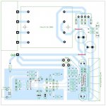
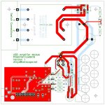
The PCB rough draft is done, but keep in mind that there probably are a couple of mistakes and a few points of disagreement between the schematic and the PCB. The over-aching goals were to make a one sided PCB to allow easier home prototyping and to use as many parts that I had readily available in my garage. I obviously cheated with the top layer and used that for jumpers (only 5, woohoo!)
The general layout should be pretty self explanatory, and breaks things into three sections: the PSU, UAB/DAC and amplifier. The USB/digital ground is isolated from the central ground via a resistor to keep as much goofiness from the USB out of the amp as possible. The LM1876 is set up with differential inputs to further reject any digital noise. I still don't really like where the speaker outputs are, but I'll worry about that later. I'll probably break up the +/- output blocks to eliminate the long ground run, but I'll see if that matters in the prototype.
Right now, I am ready for bed, so I get to double check the boards later and probably prototype later in the week if I can manage the time. That and a quick order to Digikey and I should be set!
David
PS On a side note, the initial draft used all SMP's, but after realizing that I had most of the "through hole" parts already, I switched out components and the only surface mount parts left are the PCM2707 and the crystal. Using SMP's the layout was substantially more compact, as I am sure you can imagine, and if anyone is interested, I may finish it up, but I figured through hole parts would be more universally used anyway, so I never got around to finishing the SMP version.
Attachments
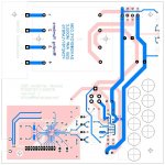
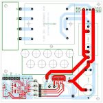
Not anything too interesting, but I finished off the SMP version of the amp. I think despite the fact that I'll have to buy a few more parts for this board, this is the one I am going with. The grounding is cleaner and the critical elements are further from the transformer with the added "shielding" of the heatsink (not that it will help too much, unless someone has some sinks made of MuMetal )
Also, I added pin headers for USB DAC out and separate inputs for the amp in case things ever need to get switched up somehow. Easier to do now that in the future!
All of the SMP's are 1206, which should be pretty easy to hand assemble. Also, I added in alternate cap pads in case I want to add/change the rail caps. I think that is about it. . .
Anyway, since this seems to have turned into a work-log, enjoy if you are following along, and I'll post more when I do something new!
David
)Also, I added pin headers for USB DAC out and separate inputs for the amp in case things ever need to get switched up somehow. Easier to do now that in the future!
All of the SMP's are 1206, which should be pretty easy to hand assemble. Also, I added in alternate cap pads in case I want to add/change the rail caps. I think that is about it. . .
Anyway, since this seems to have turned into a work-log, enjoy if you are following along, and I'll post more when I do something new!
David
Attachments
- Status
- This old topic is closed. If you want to reopen this topic, contact a moderator using the "Report Post" button.
- Home
- Amplifiers
- Chip Amps
- Compact USB DAC/Integrated LM1875 Amp